Automation Profiles: Eight Robotic Cells Assemble Engine Part
Crimping and press-fitting are not inherently difficult assembly processes-unless you have to complete them in less then 2 seconds and meet a tolerance of 1/50th the diameter of a human hair.
A cam phaser is an adjustable timing gear that uses oil pressure and a spring-loaded toothed wheel to retard and advance cam timing based on engine load and speed. In this first installment of a new series dedicated to automated assembly systems, Bruce Flesher, president of Device Tech, describes how his team met the challenge. For more information on Device Tech, call 847-683-7235 or visit www.devicetech.net.
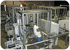
Describe the system. Power-and-free assembly system with eight cells.
What are the dimensions of the product? 5 inches long and 1 inch in diameter.
How many parts are assembled to complete the product? 22
What materials are the parts made of? Steel, aluminum, stainless steel, plastic, rubber, copper and an oil-based lubricant.
What equipment is used in the system? 11 feeder bowls; eight, compact six-axis robots; three servo-driven linear slides; two hydraulic crimping presses; three tray handling systems; a laser welder; three custom O-ring assembly systems; several pick-and-place devices; 50 pallets with RFID tags; a looping plastic-chain conveyor; multiple flat-belt conveyors; and one indexer.
What methods are used to assemble the product? Laser welding, crimping and snap fits.
What equipment is used to inspect the product? The presses are equipped with load cells and linear variable displacement transducers. The system also includes a fluid pressure gauge, RFID readers, and several photoelectric and laser sensors to detect part presence and verify completion of assembly steps.
What tests are included? Leak and flow tests.
What is the production rate? Six to seven parts per minute.
What was the most challenging aspect of designing the system? We developed a telescoping O-Ring assembly tool that can install three O-rings on different diameters, and at different elevations, at one time.
We also developed a way to wrap and laser weld a stainless steel filter around a valve housing, or snout. The filter must be square and centered, and it cannot mark or scrape the snout in any way. The snout is made of soft aluminum. The overlapping ends that get laser welded must be parallel, as well. We guide the filter in a close-tolerance fixture. Tiny rollers and a spring-loaded clamp contain and wrap the filter to just beyond the tangent point of the snout. We clamp the snout into the guide nest from above. We then sequence two folding fingers to do the final wrap of the filter from above. We also stamp an offset form on the filter to help it lay flat at the overlap. We had to leave clearance at the top of the tooling to allow the laser to weld. We weld four spots on each of the three filters. The clamp, wrap and weld process takes 3 seconds of the total 8 second cycle time.
Another challenge was to insert a precision spool into the snout with a 0.0002-inch clearance in less than 2 seconds. To accomplish this, we place the calibration ring and a spring into a nest. The nest features a single post with a radiused tip. A robot takes the spool from a tray and places it onto the post. The same robot inserts the snout into a tool on the end of a servo press. We hold the snout in the tool with vacuum. We then extend the snout down toward the spool. Just before we meet up to the spool, we turn on an air blast through the inside diameter of the snout. This creates an air curtain around the bottom port of the snout and the top of the spool. As the snout gets closer to the spool, the air pressure automatically centers the two parts to the inside diameter of the snout. Once the spool is in the snout by approximately 0.125 inch, we reverse the air pressure to a vacuum and it sucks the spool up into the snout in an instant. The servo press follows through on its stroke and inserts the spring inside the snout, along with the calibration ring, which gets pressed into the end of the snout to retain the spring and spool.
The last big challenge was getting the robots to run at rate. There are many secrets to programming that you don’t get through a two-week training course. Thank God for tech support-they made it work. Those robots can fly like maniac ninjas.
Editor’s note: This is the first installment of a monthly series profiling multistation automated assembly systems. Whether you’re a systems integrator or the in-house automation team of an OEM, if you’ve designed a system that you’re particularly proud of, tell us about it. Send an e-mail to John Sprovieri, editor of ASSEMBLY, at sprovierij@bnpmedia.com, or call 630-694-4012.
Looking for a reprint of this article?
From high-res PDFs to custom plaques, order your copy today!


