Wire Processing: Data-Centric Tools Reduce Design Costs
New software enables synchronized design data to flow seamlessly through domains and across organizations.
In the automotive industry, physical drawings are the common thread that runs through the process of designing a vehicle’s electrical system.
But, drawings are just one view of the data that accrues as a vehicle platform moves from concept to physical design and beyond. Other views are just as relevant: the procurement perspective (What parts are required for this design?); the engineering standpoint (Will this motor run when these switches are activated?); and even an auditor’s interpretation (Is this design current? Is it signed off?).
Rising cost and complexity are the key challenges in vehicle design. Increasingly, OEMs and their suppliers are learning that data-centric software tools, like Mentor Graphics’ new Capital suite, can solve these challenges by providing consistent, up-to-date data that is easily accessible from end to end.
With data-centric software, synchronized data flows seamlessly through domains and across organizations. Every tool shares a common data model. Every component in the vehicle is represented at every step in the design process. Product planners, designers, procurement agents and process auditors all draw from the same data to meet their analysis and visualization needs.
The physical wiring layout is achieved by mapping the conceptual system connectivity onto the physical design. When the overall wiring diagram is complete, individual harnesses can be designed. All totaled, there may be thousands of harness designs to support all the possible customer configurations. Of course, these must be manufactured, and the harness manufacturer-another data consumer-will analyze the build requirements to optimize costs. Similarly, the service documentation group needs to create manuals to support all of the possible variants. All these disciplines rely on consistent information accumulating across a data-centric flow.
Early in the flow, component representations are abstract. At each successive step, they become clearer, but their definitions are not cast in concrete. Many features of the emerging electrical system can and will change as the design matures. Any change to a particular component’s definition, at any single step, must be reflected in all the steps, both earlier and later in the process. For instance, does the proposed change comply with the vehicle’s original requirements? Does it add manufacturing cost? Will it be a problem in the service bay? A data-centric approach ensures efficiency when tracking, managing and validating changes across the process.
When designing a vehicle’s electrical system, engineers typically work with graphical symbols. These symbols contain details about electrical behavior that ensure the design is created correctly. From this starting point, the information will be used to constrain downstream design data and ensure that all steps in the process remain synchronous and that changes can be flagged and processed.
In our Capital suite, a Project Browser helps to manage the electrical content of the platform under development with folders for the designs at different stages in the design process, from concept to individual harnesses. It also contains multiple revisions of each design.
The same data could also be managed directly from a product life cycle management (PLM) system, but the Project Browser window provides valuable specialized functionality for cross-comparison and deep interrogation of the electrical design data that can be difficult to achieve with a PLM system alone.
Capital’s Design Browser underscores the importance of domain-specific data environments. Selecting a part’s text entity automatically locates and highlights the equivalent graphical element, even if it is not on the page currently displayed.
A tab in the Design Browser provides access to a store of electrical schematic symbols. But these are more than mere line drawings. They contain references to library definitions and electrical-analysis models that allow the designer to check for voltage drops, current flow and other specifications. A component’s library definition includes customer and supplier name information, connector interface information and other details.
Early in the design flow, every detail may not be defined, but the data-centric environment allows new information to join existing data at any time and provides structured entry forms for the purpose. The incoming data is automatically flagged and can be synchronized by the designer at every stage of the process.
At the conceptual stage, an engineer defines a host of interconnections, but intentionally does not define how these connections are physically implemented as wires and connectors. At the wiring design stage, the engineer takes the process one step further, creating a schematic of the electrical connectivity with much greater detail. The schematic draws its data from the larger flow, but incorporates details such as wire specification and the assignment of individual pins within connectors.
A connector may carry unrelated signals from several different subsystems, each being managed by several different engineers. The potential for conflict is high, and this level of complexity is difficult to control without data integration that allows the engineers to work concurrently throughout the flow.
There are hundreds of system-level and wiring-level designs in a complete vehicle platform. The discipline imposed by data-centricity makes each more manageable within its own local context and in relationship to all others like it. Within a data-centric flow, the data remains consistent as a part moves from one stage to the next. The software ensures that the designer doesn’t have to enter the same data twice. In addition, the system applies constraints and feedback to enforce data consistency among component definitions and individuals working on a project team.
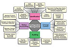
There are four major aspects of configuration control: identification, status accounting, auditing and change control.
Identification relates to the task of tracking everything in the product throughout its lifetime-from concept through end-of-service. It relates to design documentation as well as component issues, such as the supplier for a particular wire in a vehicle.
For example, with wire identification, engineers must be prevented from assigning wire or component identification names that have already been assigned to other parts. This is problematic in a drawing-centric process, because it depends on correct execution of naming rules by the engineer and demands additional checking and validating steps to prevent errors. With a data-centric approach, the software keeps track of elements continuously, preventing incorrect choices and automating the naming of parts.
Many configurations and revisions are certain to arise when dozens of electrical engineers work independently on their own designs. How does one manage all these designs? Data-centric software:
Requires engineers to define and record valid configurations in the form of specialized definitions called build lists.
Confirms that all designs are compatible, and that no design defines a wire with a reference to another design that doesn’t exist.
The latter step alone represents months of effort in a drawing-centric process. Data-centric software completes the task in minutes. With automatic build lists and revision management, data-centric software enables designs to move quickly forward in the face of burgeoning complexity.
Status accounting requires maintenance of product description records, configuration verification records, change status records, and change approval histories. Many of these functions fit naturally into the capabilities of a PLM system, but domain-specific design tools offer data-centric generation of these records at a much more granular level of detail.
With such software, as the design evolves from the complete system, through overall wiring, and into individual harnesses, part definitions become increasingly detailed. At a certain point, a “library part definition” becomes the master. For example, the library definition for a connector includes a physical description of the connector, its color, material, number of cavities, and other information. A graphical symbol is provided, as are records of revisions to the component.
Auditing includes formal qualification reviews, physical configuration audits and functional configuration audits. The audit trail is all about tracking who did what, where and when on platform design data. Three types of functionality are essential to meeting these requirements: audit trail, build lists and effectivity (when or how designs go into effect).
A data-centric audit trail lists important operations such as up-revisioning, design rule validation and harness processing, plus details like the time of day, the object being modified, and the name of the person making the change. The intent is to track major steps, such as a design release or a change in design status. Software tools offer a means to filter audit data against particular requirements, such as the platform or a particular user. In addition, the tools know the effectivity range for every design and revision, and can automatically generate build lists and complete design configurations for any given effectivity.
Change control encompasses user access control, change policy definition, design comparison and other activities.
For user access control, system administrators set up each user with a role, such as librarian, designer or project administrator. Each role can be further specialized at a deeper level of granularity. These designations are useful if, for example, it is necessary to differentiate a contractor’s access to component or design data from that of an in-house engineer.
Change policies are a cornerstone of the data-centric design process, because they control the flow of data between design stages. Change policies provide filtered, granular control of data transfers. For example, a policy might be created to control wire definition by several different groups working concurrently. The policy defines whether to ignore or accept particular wire attributes when they are submitted by another engineer or supplier working on the design.
Design comparison is valuable when validating the changes made between revisions of designs. Designs that appear to be identical may differ in their hidden attributes. Computers can process voluminous data quickly and unerringly, given good input. Graphical and attribute design-comparison tools in data-centric systems work from information that is accurate and current. They never miss critical details due to fatigue or boredom.
Data-centric processes offer an effective solution to the challenges of cost and complexity in vehicle design. Traditional record-keeping methods simply can’t keep up with the thousands of variants and millions of details in today’s vehicles. A data-centric environment integrates domain-specific tools and enterprise databases to reduce development time, eliminate systematic errors, and improve design quality. It adds up to better products at lower cost.
Wire Processing: CAD Keeps Pace With Complexity.
Assembly in Action: Software Reduces Design Times.
Automating Wire Harness Design.
In the automotive industry, physical drawings are the common thread that runs through the process of designing a vehicle’s electrical system.
But, drawings are just one view of the data that accrues as a vehicle platform moves from concept to physical design and beyond. Other views are just as relevant: the procurement perspective (What parts are required for this design?); the engineering standpoint (Will this motor run when these switches are activated?); and even an auditor’s interpretation (Is this design current? Is it signed off?).
Rising cost and complexity are the key challenges in vehicle design. Increasingly, OEMs and their suppliers are learning that data-centric software tools, like Mentor Graphics’ new Capital suite, can solve these challenges by providing consistent, up-to-date data that is easily accessible from end to end.
With data-centric software, synchronized data flows seamlessly through domains and across organizations. Every tool shares a common data model. Every component in the vehicle is represented at every step in the design process. Product planners, designers, procurement agents and process auditors all draw from the same data to meet their analysis and visualization needs.
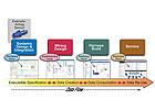
Flow With Data at its Heart
The first step in designing a vehicle’s electrical system is platform definition, in which the vehicle’s feature content is determined; options and variants are planned; and executable specifications created. From there, the proposal goes to mechanical layout, electrical design, fabrication, and ultimately to service documentation.The physical wiring layout is achieved by mapping the conceptual system connectivity onto the physical design. When the overall wiring diagram is complete, individual harnesses can be designed. All totaled, there may be thousands of harness designs to support all the possible customer configurations. Of course, these must be manufactured, and the harness manufacturer-another data consumer-will analyze the build requirements to optimize costs. Similarly, the service documentation group needs to create manuals to support all of the possible variants. All these disciplines rely on consistent information accumulating across a data-centric flow.
Early in the flow, component representations are abstract. At each successive step, they become clearer, but their definitions are not cast in concrete. Many features of the emerging electrical system can and will change as the design matures. Any change to a particular component’s definition, at any single step, must be reflected in all the steps, both earlier and later in the process. For instance, does the proposed change comply with the vehicle’s original requirements? Does it add manufacturing cost? Will it be a problem in the service bay? A data-centric approach ensures efficiency when tracking, managing and validating changes across the process.
Tracking a Part's Life Cycle
As early as the conceptual stage, a data-centric process begins to manage and track design elements as they emerge.When designing a vehicle’s electrical system, engineers typically work with graphical symbols. These symbols contain details about electrical behavior that ensure the design is created correctly. From this starting point, the information will be used to constrain downstream design data and ensure that all steps in the process remain synchronous and that changes can be flagged and processed.
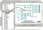
In our Capital suite, a Project Browser helps to manage the electrical content of the platform under development with folders for the designs at different stages in the design process, from concept to individual harnesses. It also contains multiple revisions of each design.
The same data could also be managed directly from a product life cycle management (PLM) system, but the Project Browser window provides valuable specialized functionality for cross-comparison and deep interrogation of the electrical design data that can be difficult to achieve with a PLM system alone.
Capital’s Design Browser underscores the importance of domain-specific data environments. Selecting a part’s text entity automatically locates and highlights the equivalent graphical element, even if it is not on the page currently displayed.
A tab in the Design Browser provides access to a store of electrical schematic symbols. But these are more than mere line drawings. They contain references to library definitions and electrical-analysis models that allow the designer to check for voltage drops, current flow and other specifications. A component’s library definition includes customer and supplier name information, connector interface information and other details.
Early in the design flow, every detail may not be defined, but the data-centric environment allows new information to join existing data at any time and provides structured entry forms for the purpose. The incoming data is automatically flagged and can be synchronized by the designer at every stage of the process.
At the conceptual stage, an engineer defines a host of interconnections, but intentionally does not define how these connections are physically implemented as wires and connectors. At the wiring design stage, the engineer takes the process one step further, creating a schematic of the electrical connectivity with much greater detail. The schematic draws its data from the larger flow, but incorporates details such as wire specification and the assignment of individual pins within connectors.
A connector may carry unrelated signals from several different subsystems, each being managed by several different engineers. The potential for conflict is high, and this level of complexity is difficult to control without data integration that allows the engineers to work concurrently throughout the flow.
There are hundreds of system-level and wiring-level designs in a complete vehicle platform. The discipline imposed by data-centricity makes each more manageable within its own local context and in relationship to all others like it. Within a data-centric flow, the data remains consistent as a part moves from one stage to the next. The software ensures that the designer doesn’t have to enter the same data twice. In addition, the system applies constraints and feedback to enforce data consistency among component definitions and individuals working on a project team.
Configuration Control
A data-centric design flow helps enterprises with configuration management. Timely and accessible data ensures that the engineer knows which design revision to work on, and that available specifications and schematics are current and compatible.There are four major aspects of configuration control: identification, status accounting, auditing and change control.
Identification relates to the task of tracking everything in the product throughout its lifetime-from concept through end-of-service. It relates to design documentation as well as component issues, such as the supplier for a particular wire in a vehicle.
For example, with wire identification, engineers must be prevented from assigning wire or component identification names that have already been assigned to other parts. This is problematic in a drawing-centric process, because it depends on correct execution of naming rules by the engineer and demands additional checking and validating steps to prevent errors. With a data-centric approach, the software keeps track of elements continuously, preventing incorrect choices and automating the naming of parts.
Many configurations and revisions are certain to arise when dozens of electrical engineers work independently on their own designs. How does one manage all these designs? Data-centric software:
The latter step alone represents months of effort in a drawing-centric process. Data-centric software completes the task in minutes. With automatic build lists and revision management, data-centric software enables designs to move quickly forward in the face of burgeoning complexity.
Status accounting requires maintenance of product description records, configuration verification records, change status records, and change approval histories. Many of these functions fit naturally into the capabilities of a PLM system, but domain-specific design tools offer data-centric generation of these records at a much more granular level of detail.
With such software, as the design evolves from the complete system, through overall wiring, and into individual harnesses, part definitions become increasingly detailed. At a certain point, a “library part definition” becomes the master. For example, the library definition for a connector includes a physical description of the connector, its color, material, number of cavities, and other information. A graphical symbol is provided, as are records of revisions to the component.
Auditing includes formal qualification reviews, physical configuration audits and functional configuration audits. The audit trail is all about tracking who did what, where and when on platform design data. Three types of functionality are essential to meeting these requirements: audit trail, build lists and effectivity (when or how designs go into effect).
A data-centric audit trail lists important operations such as up-revisioning, design rule validation and harness processing, plus details like the time of day, the object being modified, and the name of the person making the change. The intent is to track major steps, such as a design release or a change in design status. Software tools offer a means to filter audit data against particular requirements, such as the platform or a particular user. In addition, the tools know the effectivity range for every design and revision, and can automatically generate build lists and complete design configurations for any given effectivity.
Change control encompasses user access control, change policy definition, design comparison and other activities.
For user access control, system administrators set up each user with a role, such as librarian, designer or project administrator. Each role can be further specialized at a deeper level of granularity. These designations are useful if, for example, it is necessary to differentiate a contractor’s access to component or design data from that of an in-house engineer.
Change policies are a cornerstone of the data-centric design process, because they control the flow of data between design stages. Change policies provide filtered, granular control of data transfers. For example, a policy might be created to control wire definition by several different groups working concurrently. The policy defines whether to ignore or accept particular wire attributes when they are submitted by another engineer or supplier working on the design.
Design comparison is valuable when validating the changes made between revisions of designs. Designs that appear to be identical may differ in their hidden attributes. Computers can process voluminous data quickly and unerringly, given good input. Graphical and attribute design-comparison tools in data-centric systems work from information that is accurate and current. They never miss critical details due to fatigue or boredom.
Data-centric processes offer an effective solution to the challenges of cost and complexity in vehicle design. Traditional record-keeping methods simply can’t keep up with the thousands of variants and millions of details in today’s vehicles. A data-centric environment integrates domain-specific tools and enterprise databases to reduce development time, eliminate systematic errors, and improve design quality. It adds up to better products at lower cost.
ASSEMBLY ONLINE
For more information on wire harness design software, visit www.assemblymag.com to read these articles:Looking for a reprint of this article?
From high-res PDFs to custom plaques, order your copy today!


