XYZ - Software Simplifies Programming of Kinematics
|
|
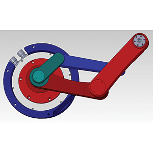
Kinematic mechanisms are lighter and quicker than Cartesian systems. New software is helping engineers integrate these
mechanisms into their designs. Photo courtesy Yaskawa America Inc.
|
However, Cartesian mechanisms are not without limitations. For one, they require a lot of space. And since two or three actuators are stacked one atop the other, when one motor is moving, the other motors are dead weight. Add the weight of the power and control cables—not to mention the payload—and that’s a lot of mass to move around.
“You can only make a ballscrew move so fast,” says Kevin Hull, senior applications engineer at Yaskawa America Inc. “And Cartesian systems need support structures, like linear bearings, that can take up a lot of space. Today, engineers are trying to make things smaller, faster, less expensive and more efficient. Kinematics is a way to do that.”
Engineers are increasingly using kinematic mechanisms to perform pick-and-place operations in assembly machines, case loaders and other equipment. A classic example of a kinematic mechanism is a delta-2 robot. The delta-2 is a parallel robot with two legs. Each leg consists of one actuated joint and two passive joints. Due to its mechanical design, this robot has only two degrees of freedom, which means that it can move only in the XZ plane.
With a kinematic mechanism, neither the motors nor the power and control cables move with the end-effector. As a result, the mechanism is lighter and quicker than a Cartesian system. And since less rotary motion is needed to create the linear motion of the end-effector, kinematic mechanisms are also more durable than Cartesian systems, says Hull.
Although kinematic mechanisms are more efficient than Cartesian systems, they are not easier to program. Because the position of the end-effector is not determined by straight-line motion, complex calculations are needed to move the tool from point A to point B.
“Most controllers are set up for a Cartesian system—you have inputs for X, Y and Z,” explains Doug Meyer, senior project engineer at Yaskawa. “Kinematic mechanisms achieve motion through the theta 1 and theta 2 axes, yet they operate in a plane. So, you have to program the system in terms of angle 1 and angle 2.”
In March, Yaskawa introduced new software that promises to simplify the process of programming kinematic mechanisms. The Kinematics Toolbox for Yaskawa’s MotionWorks IEC controllers enables engineers to program kinematic mechanisms using standard Cartesian coordinates. The controller automatically handles the mathematical translations.
Looking for quick answers on assembly and manufacturing topics? Try Ask ASM, our new smart AI search tool. Ask ASM
The toolbox includes two PLCopen control function blocks for programming delta-2 and four-bar kinematic mechanisms. The function blocks provide virtual Cartesian axes, “so engineers can create their normal application code; they just do it for virtual axes,” says Meyer. “The function block automatically translates that virtual Cartesian motion into real motion in the kinematic space.”
Ordinarily, a delta-style kinematic mechanism would require dedicated robot controller. With the Kinematics Toolbox, engineers can save that cost and control the mechanism with the same general purpose controller that’s governing other axes of motion on the machine.
The Toolbox uses the IEC6113-3 programming environment, which enables engineers write code in any of five languages: ladder diagram, function block diagram, structured text, sequential function chart and instruction list. “That makes programming easier,” says Meyer. “You can use ladder for I/O, function blocks for motion, and text for calculations and initialization.”
Looking for a reprint of this article?
From high-res PDFs to custom plaques, order your copy today!


