advertisement
How To Simplify the Process of Specifying Air Cylinders for Operation in Tight Spaces

QUICK QUESTIONS AND ANSWERS
You are up against extreme space limitations with little room for fitting an air cylinder into your current design project. Here’s a few questions and pictures to help point the way to your solution.
Q: Just how small can a compact cylinder be?
Pretty small. Short Stroke, Compact Cylinders have strokes as short as 1/16” and bores down to 1/2”.
Q: What type of work will your actuator be doing?
Will you be Pushing? Pulling? Lifting? Turning?
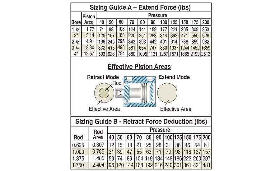
Let’s answer pushing and pulling applications first. Once you know how much force you need, you can determine the bore size or the power factor (effective piston area) of the required cylinder by using the equation:
Push Force = (Pressure Available) x (Power Factor), or
re-stated: Power Factor = Force ÷ (Pressure Available)
Looking for quick answers on assembly and manufacturing topics? Try Ask ASM, our new smart AI search tool. Ask ASM
Or you can go to the manufacturers’ catalogs for sizing guides as shown in example Sizing Guide A below;
Q: Can you use the same cylinder for lifting or pulling a load?
Not necessarily. Pulling or lifting force, calculated when the cylinder retracts, brings the rod diameter into play. As shown in Figure 1, air pressure can act only on part of the piston in retract mode because the rod blocks the middle of the piston. Thus the retract power factor is calculated as an annular ring – piston area minus rod area. Sizing Guide B shows force reductions for various rod diameters.
Q: Once you have the bore, what are your space concerns?
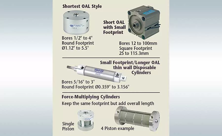
Do you want short overall length? A Small footprint or small OD? Do you need close center-to-center distance for locating cylinders side by side?
Figure 2 shows some of the envelope shapes for typical cylinders that may help to find your solution.
Q: What if the footprint is too small for a standard offering?
Force-Multiplying – cylinders have multiple pistons attached to a common shaft to multiply the output forces. Each extra piston adds length to the cylinder without changing the base footprint. If you have room for the extra length, these powerful alternatives might just do the trick for you.
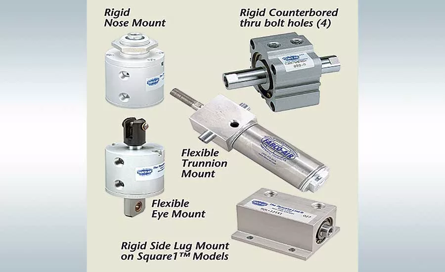
Q: How will you mount the cylinder? Will you be pushing a load, or turning a crank arm? (Answer determines type of mount needed.)
Rigid Mounting – For pushing, pulling or lifting along a straight line, we want the cylinder to be rigidly mounted. A variety of mounting styles are available for your consideration. You can bolt some cylinders to your equipment using bottom tapped holes or stand them on end and run bolts into tapped holes in the end faces. • Flexible Mounting. If turning a crank arm, the cylinder would need to pivot. Note some of your mounting choices in Figure 3 below.
Q: Must the load stop at an intermediate position?
3-Position cylinders – You’re in luck. You can get three or more rod positions from a single cylinder! Many cylinders styles are offered with 3-position options. The Pancake II® cylinder, shown here, is essentially two cylinder bodies combined in a single package. You can specify the same or different stroke lengths to set your work positions as required. Nice!
Q: What motion elements need consideration?
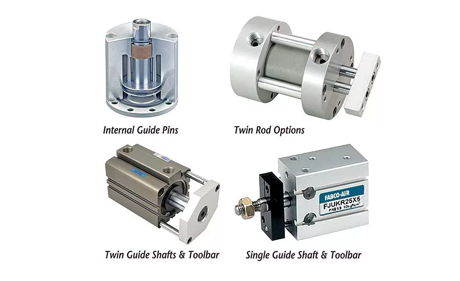
Can the load be allowed to rotate slightly?
Non-rotating options – For applications in which anti-rotation and registration are critical, note some of the convenient options available to you in Figure 4 below.
Q: Are there any adjustable stroke options? Most certainly!
Come visit us at FABCO-AIR.com to find these options as well as answers to all your automation questions. Or call us at 352-373-3578 (Email service@fabco-air.com).
Fabco-Air Solves Problems. http://www.fabco-air.com
Looking for a reprint of this article?
From high-res PDFs to custom plaques, order your copy today!


