Advances in Assembly
These innovations will help assemblers make their operations more cost-effective.


Adhesives formulated with See-Cure technology are bright blue before curing, making it easy to see where they have been applied. When cured, the color fades to clear, confirming that the adhesive is fully cured. Photo courtesy Dymax Corp.
Watch The Adhesive Cure
Two of the most vexing questions assemblers face in using adhesives are, “How can I tell where the adhesive has been applied?” and “How do I know the adhesive is cured?” See-Cure, a new adhesive technology from Dymax Corp. (Torrington, CT), addresses both of these questions.
A light-curing adhesive formulated with See-Cure technology is bright blue in the uncured condition. This makes it easy to see on substrate surfaces, in deep wells or when sandwiched between two material layers, thus answering the question of where the adhesive has been applied. Because the blue color is highly visible, simple vision systems can also be used to confirm adhesive coverage and profile prior to curing.
The blue color also shows visually when sufficient light energy has been applied to the adhesive bond area to achieve full cure. The blue color fades as the adhesive cures, ultimately turning clear upon full cure, thus answering the question of when the adhesive is cured. The rate of color change is 15 percent to 25 percent less than the cure rate to ensure that visual clarity reliably indicates full cure. As light-curing adhesives typically cure in fractions of a second, the added time for the color transition from blue to clear is negligible.
The blue colored adhesive will not stain substrate surfaces, does not affect RoHS compliance, and does not affect the biocompatibility certifications of medical device adhesives. Adhesives formulated with See-Cure technology are available in a broad range of cure speeds and cured properties. Including See-Cure capability does not affect cure speed or cured properties.
For more information, call 877-396-2988 or visit www.seeitcure.com.
Force Fields Manipulate Parts
Vibratory bowl feeders have been a mainstay in automated assembly systems for decades. However, a major disadvantage of bowl feeders is that they must be redesigned every time a new part is introduced.How much better would it be if parts could be singulated, oriented and moved on a simple, flat, vibratory plate? Such a system could be driven entirely by software. The vibrations could be programmed to handle a wide variety of parts without the need for custom tooling. More importantly, the motion of the plate could be programmed so that parts move independently of each other, thereby enabling simultaneous manipulation and assembly of multiple parts.
Researchers at Northwestern University (Evanston, IL) are bringing that ideal closer to reality. Kevin Lynch, Ph.D., associate professor of mechanical engineering, Paul Umbanhowar, Ph.D., assistant professor of physics, and graduate student Tom Vose have designed a prototype device that can control the movement of parts resting on a flat, rigid plate. By vibrating the plate in up to six degrees of freedom, the researchers can create programmable force fields that push the parts around in a controlled way.
The device consists of a round aluminum plate driven by six linear voice-coil actuators. Six legs connect the plate with the actuators. Each leg has two compliant flexure joints of flexible plastic, which are shaped to allow small-displacement spherical joint motion. Forces are transmitted to the plate through the springs and dampers of the flexure joints. Accelerometers measure the motion of the plate and provide feedback to the control system.
Through experimentation, the researchers developed a set of simple force fields. For example, one field, called “Trans,” moves parts across the plate from left to right. Another, “LineSink,” moves parts from the periphery of the table to its center line. “Circle,” as the name implies, moves parts counterclockwise around the table’s center point. These simple force fields can be combined sequentially to produce more complex motion in the parts. For example, the fields can be combined to translate parts and draw them in towards a line.
In an automated assembly system, the device could be used to present singulated parts for pick up by a robot. Parts would get onto the table from a conveyor or a vibratory track. When used in conjunction with a vision system, the table could be used to sort different parts supplied from a common source. For example, Part A might be directed toward the left corner of the table, while Part B might be directed toward the right corner.
In the future, the device could even be used to facilitate the self-assembly of parts. For example, a set of magnetized parts that fit together like puzzle pieces could be placed on the table and shaken in a controlled manner until they assembled themselves or came together in a set pattern.
The next step for the researchers is to develop an industrial version of their prototype. For more information, and to view videos of the feeder in action, click here.

A color indicator in the head of the HR SmartBolt changes from yellow when the bolt is loose to green when the bolt is tightened to design tension. Photo couresy Stress Indicators Inc.
Bolt Indicates Correct Clamp Load
Verifying the correct clamp load in a bolted joint is a perennial challenge for assemblers. Tightening with a torque wrench is quick and easy, but bolt material, lubrication, thread condition and other variables can significantly affect the clamp load produced by a given torque.However, direct tension indicators respond only to bolt tension-independent of applied torque-and clamp load is directly proportional to bolt tension. So bolt tension is actually the important result in preloading a bolted joint. Direct tension methods are based on measuring the strain in the bolt shank by directly measuring bolt elongation under tension, because bolt tension is directly proportional to the strain. The DTI SmartBolt and HR (high resolution) SmartBolt by Stress Indicators Inc. (Bethesda, MD) offer a visual confirmation that the correct tension has been achieved when the bolts are tightened.
Key to this function is a microindicator within the SmartBolt body. The microindicator is an optical absorption cell or variable-density filter. One end of the cell is brightly colored and the other end is a clear window visible as a colored indicator in the bolt head. The spectral transmittance of this fluid changes as the cell thickness changes in response to the slight elongation that occurs as the bolt is tightened. Ambient light entering the clear window is reflected from the colored end and out the window to any observer. Because the parts of the visible spectrum absorbed by the fluid change as the tension in the bolt changes, the color seen by the observer also changes.
The DTI SmartBolt and HR SmartBolt differ in sensitivity and use different colors to indicate their condition. The DTI SmartBolt shows bright red-orange with no tension and gradually darkens as the bolt is tightened until it is deep black at design tension. The accuracy is within 10 percent of design tension. The HR SmartBolt shows bright yellow with no tension, begins to turn color at 85 percent to 90 percent of design tension, is grass green at design tension, and turns nearly black when the bolt is over-tensioned. The accuracy is within 5 percent of design tension.
For more information, call 240-631-7246 or visit www.smartbolts.com.

This circuit board includes a layer of carbon composite material. The layer adds stiffness to the board and helps dissipate heat from the components. Photo courtesy Eltek
Carbon Laminate Helps PCBs Beat the Heat
As electronic devices get smaller, faster and more powerful, the thermal and structural properties of printed circuit boards (PCBs) become increasingly important. Today’s microprocessors generate a lot of heat, which must be dissipated quickly. Engineers also need to worry about mismatches in thermal expansion rates, which can fracture solder joints. And, with greater portability comes larger shock and vibration loads, which can also break delicate connections.To improve thermal management, a layer of metal, such as copper or copper-Invar-copper, can be included among the strata that make up a PCB. However, this approach has several disadvantages. For one, metal spreads heat in a circular, multidirectional pattern. Thus, for heat to be dissipated, it must first travel to the center of the board through several non-heat-conductive layers. The metal layer also adds weight, and it limits functionality by reducing the number of fine signals that can pass through the core of the board.
Now there’s an alternative: a thermally and electrically conductive carbon composite laminate for PCBs and integrated circuit substrates. Developed by Stablcor Inc. (Costa Mesa, CA), the eponymously named material is used as a plane layer, preferably the ground plane. Instead of conducting heat in all directions, Stablcor conducts heat laterally, in the X-Y plane. The material acts like a thick layer of copper in a PCB, only without the weight and high coefficient of thermal expansion of copper.
Most engineers put copper in the center of the board, to avoid expansion problems at the surface, explains Alex Mangrolia, marketing manager for Stablcor. The problem with that design is that it creates a much longer path for the heat to travel from the surface to the center. With Stablcor next to the surface layer of the board, the thermal path is very short. The heat only needs to travel from the ground pins, through the vias and a thin dielectric layer before reaching the Stablcor layer. Once the heat reaches the carbon, it moves quickly to wedge locks, chassis, heat sinks or screws. This eliminates hot spots.
Stablcor conducts heat as well or better than metal, and it’s much stiffer. In many cases, Stablcor can eliminate the need for mechanical reinforcements or stiffeners. Stiffer boards mean less warpage, more resistance to shock and vibration, and better assembly yields with high I/O components.
Another advantage of Stablcor is its low rate of thermal expansion. A standard PCB expands at a rate of 17 to 19 parts per million per degree Celsius (ppm/C). In contrast, a flip-chip die has a thermal expansion rate of 2.5 ppm/C, while the ceramic substrate on which it’s mounted expands at a rate of 6 to 8 ppm/C. That mismatch can lead to cracked solder joints if the board is subjected to thermal cycling. Carbon-embedded PCBs have an expansion rate of 2 to 12 ppm/C, so engineers can safely use ceramic ball grid arrays instead of column grid arrays, or better still, they can do away with the ceramic altogether and attach the die directly to the board.
Stablcor must be placed symmetrically within the layers of a PCB, and the material is most effective next to the surface layers. For boards with a total thickness of less than 0.035 inch, only one laminate is needed, typically in the center. For boards with a total thickness of 0.035 to 0.093 inch, two Stablcor laminates are used-one beneath each surface layer. Thicker boards require additional laminates. The material is available in a standard size of 18 by 24 inches, though larger sizes can be custom-made.
Several manufacturers are licensed to produce boards with the new material, including Cirtech (Orange, CA), North Texas Circuit Boards (Grand Prairie, TX), TTM Technologies (Stafford, CT) and Unicircuit (Littleton, CO).
For more information, call 714-524-1188 or visit www.stablcor.com.
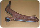
This automotive control arm was welded with the hybrid process. Photo courtesy Welding Solutions Inc.
Hybrid Welding Goes Fast and Deep
The American Welding Society defines hybrid welding as the combination of two distinct welding energy sources within a single welding process. One of the principle advantages of GMAW (gas metal arc welding), commonly referred to as MIG (metal inert gas) welding, is a high metal deposition rate. One of the principle advantages of GTAW (gas tungsten arc welding), commonly referred to as TIG (tungsten inert gas or plasma welding) is deep penetration. The Super-MIG process, from Welding Solutions Inc. (Madison Heights, MI), combines the two methods, their power supplies and controls, and a robot from either Fanuc or ABB to offer assemblers the best of both worlds.The hybrid welding unit comprises a nonconsumable tungsten electrode typical of TIG welding within a specially configured GMAW torch. This electrode establishes a plasma arc at the leading position of the weld seam, creating a keyhole and weld puddle in the parent material. The GMAW arc follows, feeding wire that melts into the puddle and fills the gap. The result is deep penetration into the weld seam by the plasma arc and plenty of filler metal deposition from by the GMAW arc to finish the weld.
Operation is electrode negative for the plasma arc and electrode positive for the GMAW arc. This creates a magnetic force that deflects the plasma arc toward the front of the weld pool, compensating for the natural tendency of the plasma arc to trail behind the torch axis during high-speed welding. The interaction between the plasma arc and the GMAW arc also promotes wire heating and spray transfer of the filler metal.
Control interface software allows an operator to program the torch to switch between plasma, GMAW or hybrid welding modes, using either the plasma or GMAW power source. The hybrid process also reduces part distortion because it produces a narrower heat-affected zone than either GMAW or plasma welding alone.
For more information, call 248-585-9966 or visit www.weldingsolutionsinc.com.

The Camera Module Assembly and Test station automatically assembles and tests digital camera modules for cell phones, automotive safety systems and other products.
Cell Automates Digital Camera Assembly
Automation Engineering Inc. (Wilmington, MA) has developed a new automated assembly and test station for digital camera modules. These modules are used in cell phones, automotive safety systems, medical devices and other products. The Camera Module Assembly and Test (CMAT) station can produce multiple camera models with minimal changeover requirements. The station’s placement head moves in six degrees of freedom to position a lens atop a camera sensor on a printed circuit board. This ensures an even focus across the focal plane. The stations can also install piezoelectric, voice coil or other actuators for automated focus and zoom.The CMAT’s interface electronics support industry-standard communication buses, as well as emerging standards, such as the Standard Mobile Imaging Architecture. The station’s software includes modulation transfer function analysis and advanced algorithms to calculate focus scores in the center and four corners of an image. This enables rapid and optimal alignment of the lens to the camera sensor, at a far better cycle time and repeatability than can be done manually.
Other quality tests, such as particle checking, distortion measurement and color verification, can also be done, once the lens is in focus. Performing these tests during alignment helps screen out bad components and assemblies earlier in the manufacturing process.
For more information, call 978-658-1000 or visit www.aeiboston.com.

An automated assembly cell with two robots builds Fan-Roll-Pitch assemblies for six-axis robots. Photo courtesy FANUC Robotics America Inc.
Robots Build Parts for Robots
FANUC Robotics America Inc. (Rochester Hills, MI) recently put into operation a cell that automatically assembles parts for its painting robots. The cell includes an M-16iB/20 robot, an LR Mate 200iC robot, their control systems, force sensors, an intelligent parts feeder and an iRVision machine vision system. The cell assembles the Fan-Roll-Pitch (FRP) unit, which consists of a servomotor and gear reducer, and in some cases a pinion gear and pinion retainer. The FRP assemblies drive the minor axes of the paint robots and some styles of integrated gear pumps that feed paint.The FRP cell is set up to build 34 different FRP assemblies. Parts for 12 FRP assemblies are loaded onto a parts cart with one complete set of parts for each assembly roughly located in one of 12 slots on the cart. The build data are stored in a database and an operator enters the numbers for each FRP assembly to be built via a web screen, which calls forth the appropriate build data.
When production begins on a new set of FRP assemblies, the M-16iB robot first locates the cart using 2D and 3D iRVision. The servomotor and gear reducer are unloaded, and their position and orientation determined by the vision system. Part numbers are confirmed by another camera, and the two are assembled. A six-axis force sensor on the end-of-arm-tool feeds data back to force control algorithms to ensure that the two are correctly mated. The M-16-iB also picks the correct fasteners from an intelligent parts feeder and hands them off in space to the LR Mate 200iC, which installs the fasteners using an integral servo-controlled nut runner.
The pinion gear and retainer, if required for the specific FRP assembly, are unloaded and installed, also using force control. Any failure during an assembly sequence results in the entire assembly being automatically rejected to the reject station, where it can be inspected, and the assembly cell moves to the next slot in the cart. As each FRP assembly is completed it is loaded back onto the cart in the same slot that held the components. Then the parts in the next slot in sequence are processed. Cycle times vary from 6 to 10 minutes depending on whether the particular FRP assembly includes a pinion gear, and on how long it takes the robot to find parts.
For more information, call 248-377-7151 or visit www.fanucrobotics.com.

A new blind rivet saves money by wasting less material on spent mandrels.
Design Cuts Cost of Blind Rivets
Open-end, break-stem blind rivets and the tools for installing them have changed very little in the past 70 years. Minor variations, such as closed-end and multigrip rivets, have been introduced to satisfy specific applications, and setting tools have become lighter, faster, stronger and more intelligent.Most of these innovations have focused on reducing the cost of installing the rivets. Little attention has been given to reducing the cost of the fastener itself. That’s ironic, considering raw material costs are rising and 90 percent of the mandrel is discarded. Now, a new blind rivet designed by Manchester Consulting Group (Manchester-by-the-Sea, MA) promises to save money by wasting less material on spent mandrels.
Compared with current rivets, the mandrel on the new rivet is 30 percent to 50 percent shorter. The other features of the new mandrel-material, diameter and break load-are the same as with existing blind rivets, and the shorter mandrel has no effect on the grip force or other fastening characteristics of the rivet itself. The only difference is that less steel or aluminum wire is wasted in the setting process.
The new rivet can be installed with existing rivet-setting tools. However, they must be retrofit with a special nosepiece and housing capable of handling, gripping and pulling the shorter mandrel. In addition, an even shorter mandrel can be used with a stepped setting process and an automatic setting tool.
For more information, call 978-526-1155.
Looking for a reprint of this article?
From high-res PDFs to custom plaques, order your copy today!


