Selecting Retaining Rings
Consider several technical factors to ensure that the right type of retaining ring is used in each fastening application
Engineers are challenged daily to come up with economical product designs that reduce weight, size, raw materials and labor. This competitive mandate affects every design facet, including the fasteners needed to hold components in place.
One style of non-threaded fastener that has been widely used to accomplish these goals is the retaining ring. A circular fastener, this ring is installed in a groove to hold components on a shaft or inside a bore. It holds gears, cams, and pulleys on shafts, and it keeps bearings, valves, nozzles and locks inside housings. Knowing which retaining ring to use in a given fastening situation can greatly contribute to the overall effectiveness and economy of a design.
Groove Depth and Load Conditions
Just as a screw needs a correctly tapped hole, a retaining ring needs properly cut grooves to ensure the best performance. Both groove walls should be parallel and perpendicular to the axis of the shaft or housing.
Groove depth should be held to specifications because the depth and the groove bottom radii determine the amount of support the load-bearing groove wall will provide. The edge margin, which is the distance of the groove from the end of the shaft or housing, must be calculated to provide sufficient material to resist shearing even under maximum loads.
Because retaining rings most often fail due to deflection, it’s important to understand how different conditions affect capacity thrust. Parts with sharp corners provide ideal contact with the protruding portion of the ring and, therefore, the best load support.
Parts having a radius or a chamfer compromise thrust capacity. When a load is applied to the retained part that contacts the ring at its outer edge, it creates a lever action against the loaded groove wall. Under extreme loads, this can lead to deflection of the ring and ultimately to failure. If these conditions exist—and this should be carefully investigated before the design is completed—it may be wise to use a reinforced retaining ring.
Equally important to correct groove preparation is the selection of ring types best suited for specific load conditions. While many ring styles share common design characteristics, each has its own special features that must be considered in relation to the individual design.
Looking for quick answers on assembly and manufacturing topics? Try Ask ASM, our new smart AI search tool. Ask ASM
For instance, where loading conditions call for maximum groove engagement, basic rings will be the best choice. However, where the load isn’t critical, but, the lug protrusion of the basic rings creates an interference problem—or where a uniformly protruding higher shoulder is of importance—preference should be given to inverted rings. It is common for such rings to be used in low-load-capacity applications where aesthetics are the main concern. Basic and inverted rings are interchangeable as far as groove dimensions are concerned.
In cases of heavy loads, the reinforced ring will outperform the basic ring because of its greater section height, lug shape and thickness. This ring may also remedy instances of fatigue failure.
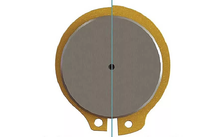
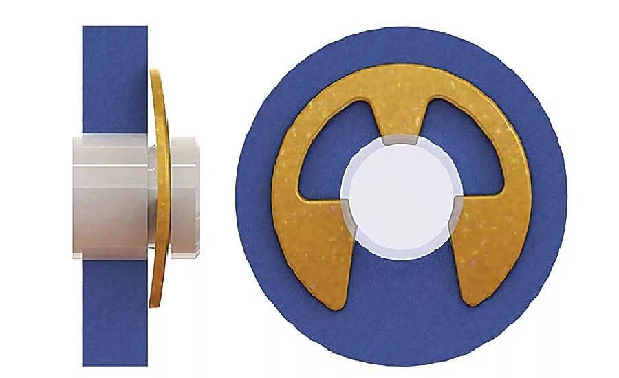
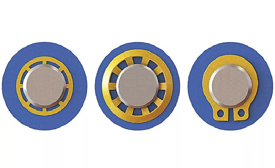
Radially installed rings also vary. The crescent C-ring is preferred where space is at a premium and loads are not very heavy. This type of ring is also more tamper resistant.
The E-ring, which is a C-ring with notches on each side of a bottom center piece, is ideal for large shoulders. A reinforced E-ring is best for applications characterized by high vibration, speed and cyclic loads.
The reinforced ring is interchangeable with the E-ring but grips the groove bottom with 3 to 5 times more radial force and has greater resistance to fatigue failure. In most cases, its outside diameter or shoulder is larger than the E-ring’s, which is another factor to consider. All three styles are available in taped cartridges for assembly with dispensers and applicators.
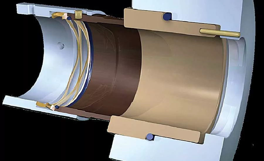
Bowed, Beveled or Self-Locking
Retaining rings can be used to compensate for accumulated tolerances or wear in the assembly, as well as to exert pressure against the retained parts. Most retaining rings are made from spring materials and are heat-treated to retain their resiliency.
Bowed rings can be flattened under pressure and will return to their set height when pressure is released. When the ring is flattened either partially or completely, it exerts counterpressure in much the same way as a spring, taking up end-play.
Bowed rings produce a compressive force to reduce chatter and vibration, and compression will vary, depending on the application. Flatter rings indicate that the retained parts were slightly longer and the rings adjusted themselves to this condition. Because of their resiliency, bowed rings will follow any axial movement of the retained part within the limitations of the bow height. However, precision loading is not the only design goal for their use.
Some retaining rings combine the features of radial installation with end-play take-up. For example, a basic E-ring can be bowed over its horizontal axis and pushed into the groove from the side of the shaft. This will exert axial pressure against the retained part.
Beveled rings serve essentially the same purpose, but they work on a different principle. Engineers take advantage of the ring’s spring characteristics, but in the ring’s own plane. The internal ring has a 15-degree bevel along the outer periphery; the external ring along the inner edge. The groove profile corresponds to that of the ring, with the beveled wall bearing the load. Here, too, the calculation of groove location is of utmost importance.
Minimum groove engagement is when the ring is seated to at least half the groove depth. The internal ring is compressed to less than its free diameter, whereas the external ring is spread to more than its free diameter. The spring properties of the rings will cause the internal type to open and the external type to close more completely, in each case exerting axial pressure against the retained part.
The groove location must be precise to prevent full bottoming of the ring in the groove. The ring acts as a wedge between the groove wall and the part, which it rigidly locks. This assembly will not breathe, so to speak, as it would with a bowed ring that may deflect under load.
The beveled edge of the ring moves along the beveled groove wall for further end-play take-up, until it conceivably reaches the position of maximum groove engagement. Then it cannot back out, even under load.
Bowed rings offer greater end-play take-up than beveled retainers, which also do not work well in high-rotational-speed applications. However, beveled retainers offer rigid end-play take-up and should be considered where cyclic loads occur.
Self-locking retaining rings are used on shafts without grooves and come in standard, reinforced push-on and grip versions. These simple circular rings have a flat rim, will support moderate static loads and are used widely because of their relatively small outside diameter.
Reinforced circular self-locking rings have a curved rim and handle greater loads even if some vibration is present. However, they have a larger outside diameter. Both types of self-locking rings work on the same principle: The prongs resist counterpressure by digging lightly into the shaft, allowing fasteners to only move in one direction. Self-locking rings should be used on non-hardened or soft shafts and, in most cases, must be destroyed to be removed.
A grip self-locking ring can be moved in either direction and its position adjusted after installation by using retaining ring pliers that fit into the lug holes. This type of ring can be used over and over again, making it more suitable for applications where components may have to be disassembled for repair or maintenance.
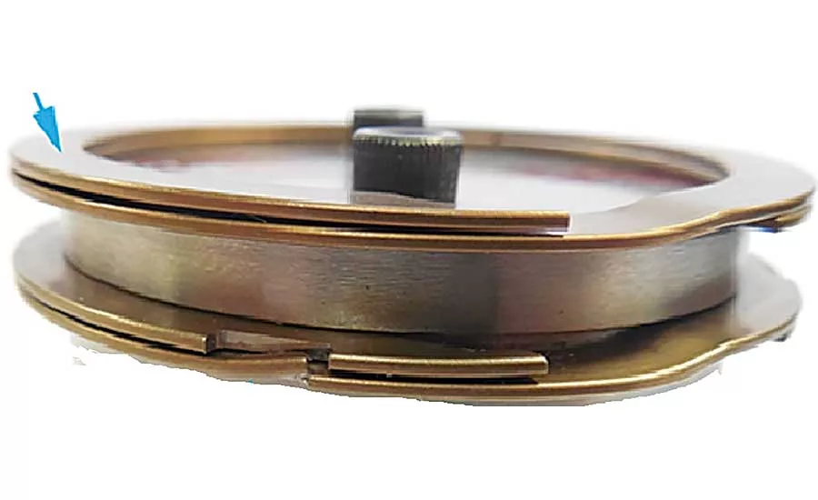
When to Get Wavy
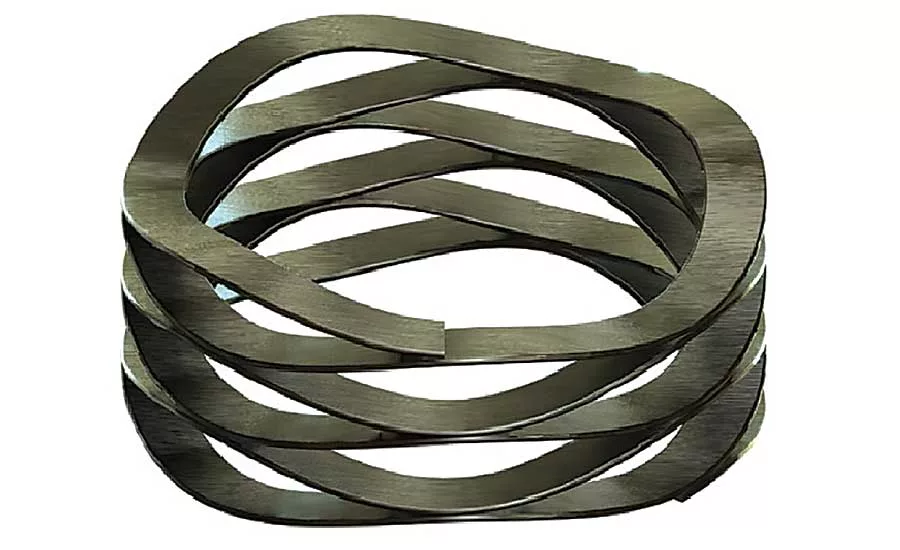
A variation of the retaining ring is the wave spring, which is a spiral ring with an axial wave form. It comes in single- and multi-turn versions, and is made from flat wire.
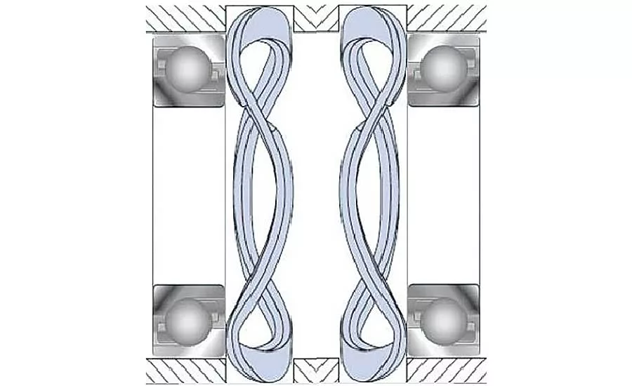
Single-turn springs often take the place of stamped wave washers. Applications include bearing preload, connector and fluid power seals, as well as noise and vibration attenuation. Multi-turn wave springs usually replace coiled springs or stacks of disc springs, and are used in mechanical seals, and power transmission and fluid power systems.
The main advantages of wave springs is their excellent force-to-work height ratio. Well-designed wave springs can produce the same or even greater forces
as coiled springs, whose work heights are up to twice as tall.
Wave springs produce a consistent force across a wide range of deflections, and their deflection curves have a wider, flatter linear force region than either coiled or disc springs. Also, because wave springs transmit spring forces only in the intended axial direction, they don’t suffer from the torsional loading and twisting that can make conventional coil springs less effective.
Consider a few examples where this feature is especially useful:
Fishing Reels. Consistent spring force allows the reel to operate smoothly and eliminate drag. In contrast, coil springs start out linear and then plane up at the end of the drag curve, which means the final 30 percent of drag adjustments are not possible. Using a wave spring offers finer control with a more linear curve—resulting in smoother drag and better performance.
Gear Sets. Within a gear set, using a wave spring will allow linear adjustments over the entire force range. In contrast, coiled spring designs can only enable fine linear adjustments at the beginning of the force range.
Slip Clutches. When using a slip clutch to extend the life of other machine components, it is critical for the clutch to react quickly based on preset torque values. Because wave springs offer the ability to make extremely fine linear adjustments, the slip clutch may be set to promptly engage once the specified torque is reached.
Flow Valves/Safety Valves. Flow valves and safety valves must open in a reliable and repeatable manner at predefined pressure points. Wave springs make this possible by enabling fine and accurate linear adjustments.
Quick Connectors. Bayonet style connectors and other quick connectors need to open at preset, safety critical torque values. Wave springs may be used in these designs to provide accurate linear adjustments that prevent such connectors from prematurely opening.
Other Benefits
Wave springs offer assembly advantages, as many are able to self-locate in bored holes or on shafts. The springs also save considerable axial space. In static applications, a wave spring will typically need just 50 percent of the work height of a coil spring to deliver an equivalent force. In dynamic applications, the work height advantage is typically about 30 percent.
The reason for the difference is because of the multi-turn wave spring design. To minimize the bending stresses in dynamic applications, the wave spring will typically require more turns than in a static application. And more turns result in additional work height.
Spring elements typically exhibit consistent linear and nonlinear force behaviors, depending on their deflection. This linear behavior can be graphically shown on the spring’s load-deflection curve.
In general, the broader and flatter the linear region of the curve, the easier it is to hit specific spring force requirements. Wave springs have a clear advantage in this department. They typically have a linear force deflection of between 30 and 70 percent. Having a predictable spring force allows the seal designer to strike the balance between excess wear from too high a preload and leaks from too low a preload. Mechanical seals, for example, successfully use wave springs to preload the sealing surfaces.
A side benefit of predictable force involves dimensional tolerances for the cavities and shafts that hold spring elements. These tolerances are often driven by the need to accommodate the spring’s force-to-work height requirements.
By specifying wave springs that produce relatively consistent force across a range of deflections, it’s often possible to loosen dimensional tolerances on spring cavities and shafts. This ability represents a major, but often overlooked, cost factor in favor of wave springs.
Whenever a coil spring is compressed to its work height, loads are torsional and in the axis of compression. These torsional loads can cause the pre-loaded component to rotate in use, potentially resulting in excess wear, as well as decrease the spring’s working load.
Wave springs don’t have this issue. Their wave forms can only compress axially, in some cases changing their diameter slightly.
When compared to a traditional disc spring, multi-turn wave springs offer far more travel. A single multi-turn wave spring can easily replace the assemblies that use multiple disc springs to achieve the necessary travel.
Most applications require relatively short travel distances, usually less than 1 millimeter. But, some suppliers have engineered multi-turn wave springs that offer up to 50 millimeters of travel.
Replacing a stacked disc spring assembly with one wave spring can allow an engineer to save money and improve product quality. Not only does the single spring cost less to install than the stacked disc springs. It also reduces the chance that the wrong number of disc springs will make it into a finished assembly.
Wave spring stiffness is determined by material thickness and type, and the number of waves per turn of spring. An engineer can easily dial in a required stiffness by optimizing the number of waves per turn using well-known design formulas.
Increasing the number of waves per turn does have an influence on free height and compressed diameter of the wave spring. Specifically, more turns increases the hysteresis since each wave has some friction associated with it.
All of these effects can be easily offset, though. Free-height and diameter can be accounted for during design, and hysteresis can be eliminated by presetting the wave spring; that is, compressing to its work height over several cycles.
Stamped products require tooling, but, wave springs can be customized on the fly by changing the parameters of the coiling equipment. This ability allows engineers to specify custom wave springs without worrying about cost or delays associated with custom tooling. This capability is yet another cost factor weighing in favor of wave springs.
Whatever the fastener requirement, engineers can find a retaining ring that can meet it. The challenge is to find the right one that performs according to specifications and delivers the expected economies. Carefully considering the rings described above is a solid first step to achieving that objective.
Looking for a reprint of this article?
From high-res PDFs to custom plaques, order your copy today!


