Wire Processing
Cobot Reduces Cycle Time, Enhances Ergonomics
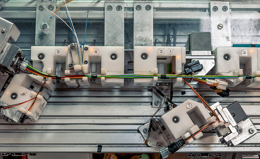
Harness taping operation is improved with collaborative robot.
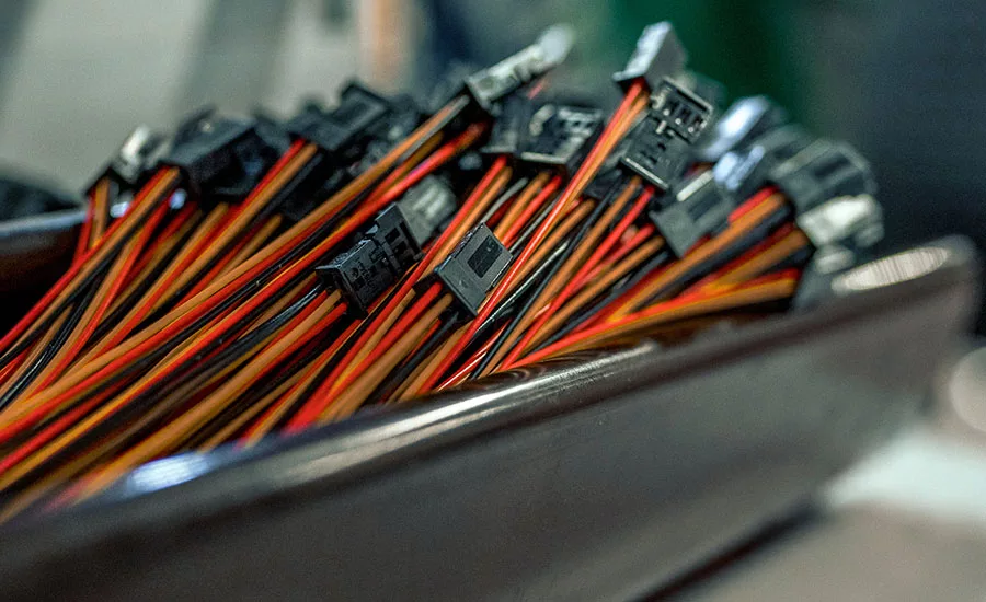
Terminated wires await assembly into a harness.
Despite myriad advances in automation, wire harness assembly remains a largely manual process. That’s unfortunate, because some level of automation could improve both productivity and ergonomics.
To prove that point, we set out to convert a manual workstation for wire harness assembly into a semiautomated station aided by a collaborative robot. Our goals were to reduce cycle time and make the station safer and less physically taxing for assemblers. We also hoped to provide engineers with a quick and easy way to assess the potential of cobots for improving ergonomics, safety, quality and economics in various applications.
For our project, we worked with Elvez, wire harness manufacturer in Višnja Gora, Slovenia. The company supplies assemblies to numerous OEMs, including BMW, Mercedes, Volvo, Scania, Hella, ZKW, Deere, PSA, Renault, Kärcher, Mahle and McLaren.
For one customer, Elvez assembles wire harnesses on a manual line with two stations. The line typically runs six days per week with three shifts per day and eight hours per shift. On average, this setup produces 900,000 harnesses annually, but that can vary from 750,000 and 1,050,000 harnesses per year, depending on demand. The cycle time is 40 seconds per harness.
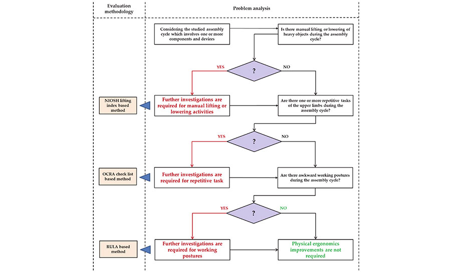
This decision tree provides a framework for identifying nonergonomic tasks that could be improved with the help of a collaborative robot. Source: Free University of Bozen-Bolzano
The assembly process requires workers to bundle three wire subassemblies with a taping tool. A worker sequentially inserts the subassemblies into a dedicated jig and then applies tape at seven spots. The process consists of 19 tasks:
- Picking up the first wire harness (1) and positioning it in the jig (2).
- Picking up the second wire harness (3) and positioning it in the jig (4).
- Adjusting the wire harnesses (5).
- Picking up the taping tool (6), applying tape at one spot (7), and putting down the tool (8).
- Picking up the third wire harness (9) and positioning it in the jig (10).
- Picking up the taping tool (11), applying tape at six spots (12-17), and putting down the tool (18).
- Removing and storing the completed wire harness (19).
Evaluating the Potential of Cobots
Our first step was to assess the ergonomics of the existing assembly process. Ultimately, we would want the cobot to handle the most physically demanding tasks.
To do that, we began with the ergonomic assessment method outlined in ISO Technical Report 12295. We focused primarily on the neck, trunk and upper limbs, concentrating on handling heavy objects, repetitive tasks, and awkward postures.
Looking for quick answers on assembly and manufacturing topics? Try Ask ASM, our new smart AI search tool. Ask ASM
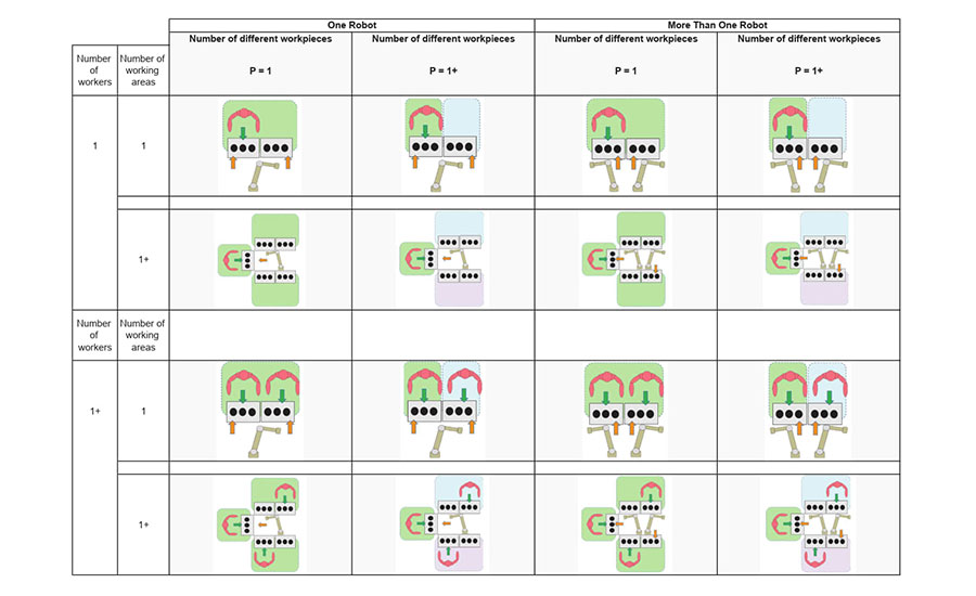
Any new line layout should be designed based on the number of robots; the number of different workpieces; the number of workers; and the number of working areas. By combining these four production variables, it is possible to identify 16 different layouts for a collaborative workstation. Source: Free University of Bozen-Bolzano
We used the following tools in our assessment:
- the National Institute for Occupational Safety and Health (NIOSH) equation for manually lifting objects.
- the Occupational Repetitive Action (OCRA) checklist for repetitive tasks.
- the Rapid Upper Limb Assessment (RULA) for working postures.
Our goal was not to calculate occupational risks, but rather to determine which tasks would be best suited for the robot and which could be left for people.
From there, we developed a “quick assessment algorithm” intended to help engineers identify assembly tasks that have the potential to be performed in collaboration with a robot. The algorithm is based on the analysis of five process-critical issues (PCIs) covering safety and ergonomics, product and process quality, and economics.
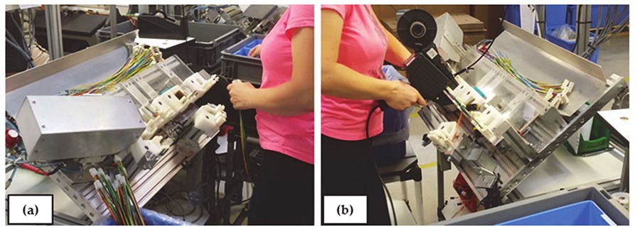
At Elvez, harness assembly tasks can be classified into two groups: insertion (a) and taping (b). Photos courtesy Free University of Bozen-Bolzano
The five PCIs are as follows:
- Are there ergonomic problems related to lifting objects, repetitive tasks of the upper limbs, or awkward working postures?
- Are there occupational risks to the operator’s safety or health that are not properly managed?
- Does the task involve a high level of monotony or a low level of skill?
- Is product quality inconsistent?
- Is there a high level of non-value-adding activity or a low level of productivity?
Engineers should score the five PCIs for each task of the assembly process. The score is an integer from 0 to 3. A score of 0 means that there are no possible improvements for the task; a score of 3 means the task has extreme potential for improvement.
The potential value of human-robot interaction in an assembly process can then be calculated as a weighted sum of the scores given to the five PCIs for each task in the process. A score of 0 means no potential value. A score of 1 to 8 has low potential value. A score of 9 to 17 has modest potential value. A score of 18 to 26 has good potential value. And, a score of 27 to 36 has high potential value.
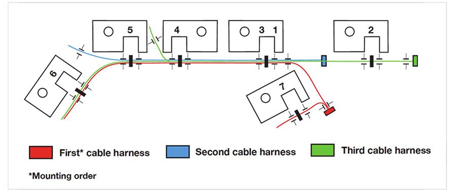
This drawing shows the layout of the assembly jigs, the position of the wires, and the taping spots. Source: Free University of Bozen-Bolzano
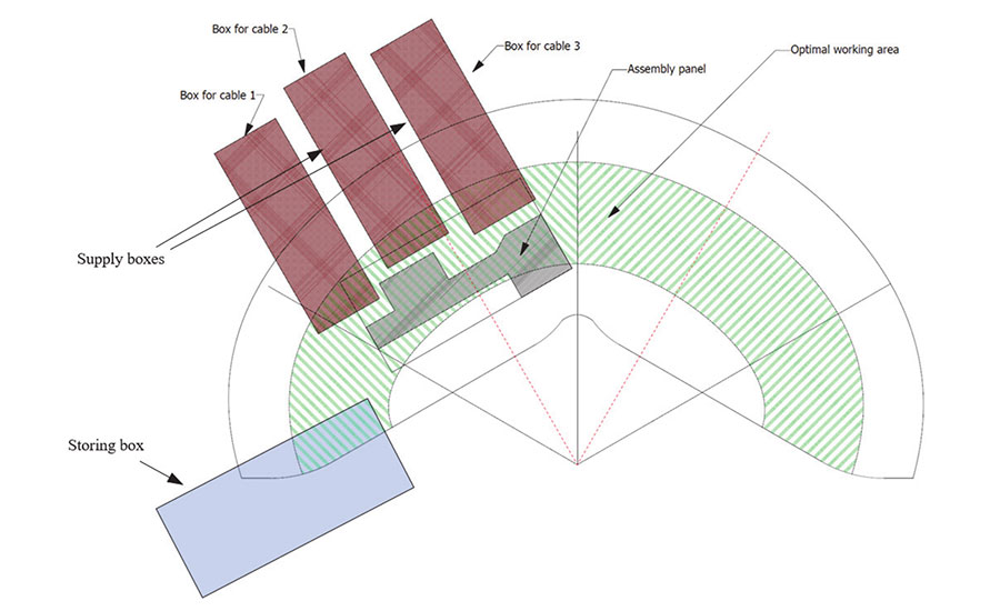
This drawing shows the layout of the new area the assembly station. Source: Free University of Bozen-Bolzano
Workstation Redesign
Since the assembly process did not require manual lifting of objects weighing 3 kilograms or more, the NIOSH evaluation was not necessary. However, we did perform OCRA and RULA analyses. With the exception of tasks 2, 9 and 18, each assembly task needed improvements in working postures.
For simplicity, we divided the 19 tasks into four groups, since many of them are the same operation repeated in different moments. The four groups were as follows:
Group 1: picking up and positioning the subassemblies (tasks 1-4 and 9-10).
Group 2: adjusting the harnesses (task 5).
Group 3: taping (tasks 6-8 and 11-18).
Group 4: removing and storing the completed wire harness (task 19).
We then scored the five PCIs for each group. Groups 1 and 3 received the highest possible score, 3, for PCI 1 (ergonomics). All the groups received a score of 0 for PCI 2 (health and safety), and all the groups received a score of 2 for PCI 3 (monotony). For PCI 4, group 3 received a score of 2, while the remaining groups scored 0. Finally, groups 1 and 4 received a score of three for PCI 5 (non-value-adding activity). Group 2 scored 0, while group 3 scored 1.
Totting up the scores, it’s clear that all four task groups show good potential for robotic automation, particularly group 1 (loading the subassemblies) with a total score of 18 and group 3 (taping) with a total score of 20.
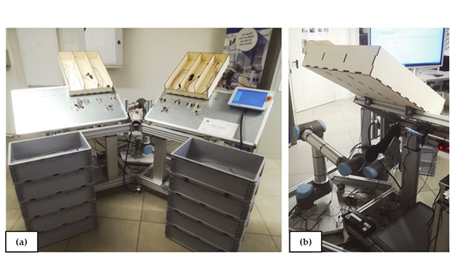
These photos show the front (a) and back (b) of our laboratory prototype for the new collaborative workstation. Photos courtesy Free University of Bozen-Bolzano
When technical feasibility is also factored in, the group 3 tasks—taping—emerge as the clear target for automation.
With that in mind, we redesigned the assembly line so that a person would load and unload the wire assemblies and a cobot would handle the taping. Our layout consists of one cobot, one assembler, and two workstations.
We chose this arrangement for several reasons:
- Only one kind of product needs to be assembled.
- The company wanted to improve productivity without increasing costs.
- The small size of the assembly area (500 by 300 millimeters) might lead the worker and the cobot to hinder each other, preventing a safe sharing of space.
- The sequentiality of most of the tasks makes it impossible to parallelize operations between the assembler and the cobot.
Having two workstations overcomes those issues. Indeed, while the assembler is loading and unloading one fixture, the cobot is working on the other.
We designed the new workstations according to the guidelines in ISO 14738. Both the assembly areas and the subassembly bins are within easy reach of the operator, which optimizes working postures.
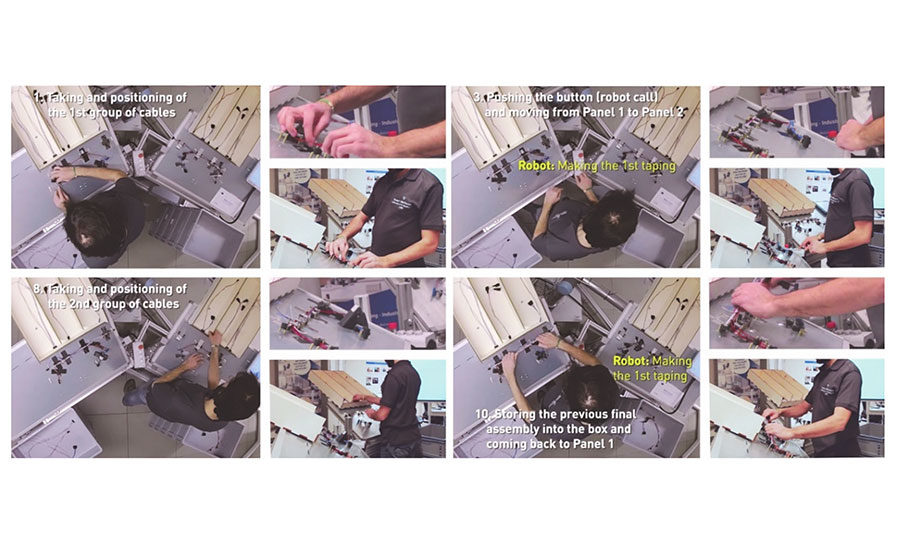
These images show workers interacting with the new layout. Photos courtesy Free University of Bozen-Bolzano
The assembly area is inclined at 30 degrees to the horizontal, to minimize twisting of the assembler’s wrist. The angle with respect to the vertical axis between the two assembly areas is 120 degrees. This allows the assembler to work on both fixtures with a minimal trunk twist and without colliding with the adjacent panel. Finally, the workstation height, as well as the fixture positions are adjustable to fit each assembler.
The cobot is located at the back side of the workstation, while the assembler is at the front. The assembly areas are located between them. The cobot is located on the floor and moves towards the fixture from below.
To reach the taping zones of both fixtures, the robot is located between them. This reduces the possibility of the cobot colliding with the assembler’s head. However, if the assembler is seated, the cobot could collide with his legs. To avoid that, the assembler can sit on a high stool, or he can work standing.
A jig secures wires prior to taping. Photo courtesy Elvez
Better Ergonomics, Faster Throughput
We tested the redesigned assembly cell in our lab prior to implementing it at Elvez. Two volunteers assembled multiple wire harnesses with the help of the cobot.
The new cell was clearly more ergonomic. Compared with the previous layout, OCRA scores improved by 12 percent for the right side and 28 percent for the left side. Similarly, the RULA scores for awkward postures also improved. Compared with the previous layout, the RULA scores were reduced by 50 percent for the left side and 57 percent for the right side.
Cycle time also improved, from 40 to 35 seconds per part, a 12 percent gain that equates to 1,460 hours per year.
Although our redesigned workstation performed satisfactorily, the cycle time could be shortened further by optimizing the cobot’s motion trajectories and developing a taping tool specially for robotic applications. Reducing the robot’s cycle time by just 1 second could save 292 hours of working time annually.
Editor’s note: This article is a summary of a research paper co-authored by Luca Gualtieri, Ph.D., deputy head of the Smart Mini Factory laboratory; Ilaria Palomba, research assistant; Fabio Antonio Merati, research assistant; and Erwin Rauch, Ph.D., professor for smart and sustainable Manufacturing. To read the entire paper, click here.
Looking for a reprint of this article?
From high-res PDFs to custom plaques, order your copy today!


