New technology lets assemblers capitalize on the ergonomic benefits of pulse tools without sacrificing requirements for accuracy and error-proofing.

Pulse tools have always been known for their ergonomic benefits and high run-down speeds. However, if fastening accuracy was a top priority, particularly on softer joints, conventional wisdom dictated that assemblers were better off with a DC electric tool or a pneumatic tool with an automatic shut-off.
Now, thanks to technological advances, assemblers can have their cake and eat it, too. They can realize the ergonomic and productivity benefits of pulse tools, without compromising on accuracy, control or data gathering for quality assurance.
“Pulse tools now compete for the entire range of fastening applications,” says Mark W. Lehnert, president and managing director of SigmaSix LLC (Rochester Hills, MI). “No longer does ‘important’ or ‘critical’ mean that DC tools are needed.”
Pulse tools are discontinuous-drive tools. They apply torque in increments rather than one continuous effort. When the fastener is running free, the tool isn’t pulsing, and the driveshaft moves very fast. A free speed of 4,000 to 8,000 rpm is typical for pulse tools, with some pistol-grip models topping out at 10,500 rpm. Once the fastener is snug, the tool begins pulsing, applying short bursts of torque lasting a few milliseconds. Depending on the joint, 10 to 15 pulses is usually enough to tighten a fastener.
“Essentially, the tool is tapping the fastener into place,” says Alan Hirschmugl, training and marketing manager for AIMCO (Portland, OR).
The source of the pulses is a unique hydraulic mechanism that consists of two rotating, cylindrical parts, explains Robert Arthur, vice president of Michigan Pneumatic Tool Inc. (Detroit). The first part, called the casing, has an oblong inner chamber filled with hydraulic fluid. It’s connected to the tool’s motor. The second part, called the anvil, fits inside the casing. It’s connected to the tool’s driveshaft. The anvil is bisected by two blades that are pushed outward by springs. These blades separate the chamber into two halves. As the casing rotates, the anvil’s blades contact the inner wall of the chamber.
When the tool is running at free speed, the casing and anvil rotate at the same rate. At this point, the blades are not touching the inner wall of the casing, and there’s no pressure on the hydraulic fluid.
As the fastener provides resistance to rotation, the anvil slows down, but the casing continues at its original speed. The blades are pushed inward toward the anvil’s center, compressing the springs. The oblong shape of the chamber combined with the compression of the blade springs reduces the volume within the chamber and increases pressure on the hydraulic fluid.
As the casing continues to rotate, fluid pressure builds and the anvil begins to hesitate slightly. Hydraulic pressure builds, pushing against the blades and forcing the anvil to rotate. When the anvil is displaced 90 degrees from the casing, the blades are fully compressed at the seal point-the narrowest section of the oblong chamber. The fluid reaches maximum pressure, and the anvil comes to a near stop. At this point rotational force on the anvil is also maximized.
When the anvil pushes past the seal point and resumes moving forward, the blades are again forced outward. Fluid pressure drops, and the anvil accelerates, starting another pulse cycle.
The advantage of this design is that the hydraulic fluid absorbs most of the vibration from the fastening process. And, because torque is applied in short pulses, torque reaction is minimal or nonexistent.

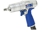
Most pulse tools now have an automatic shut-off that triggers when pressure in the hydraulic fluid reaches a certain level. Photo courtesy Michigan Pneumatic Tool Inc.
New and Improved
Over the past decade, tool suppliers have tweaked the design of the pulse unit to make it smaller, lighter, more powerful and less maintenance-intensive. Some suppliers have added extra blades to the anvil or extra vanes to the air motor.In the latest pulse tool from Atlas Copco Tools & Assembly Systems (Auburn Hills, MI), cams replace the springs supporting the anvil blades. “Cams are a little more durable than springs,” says Michael W. Moore, product manager for pneumatic assembly tools at Atlas Copco.
In the newest pulse tool from AIMCO, the anvil blades are tipped with cylindrical roller bearings, which reduce friction and wear. In addition, the pulse mechanism includes an accumulator, which keeps the hydraulic fluid at a constant temperature.
“Hydraulic fluid is just like the oil in your car-when it heats up, it breaks down,” says Hirschmugl. “By keeping the fluid at a constant temperature, it lasts longer. Ten years ago, we recommended changing the fluid after every 150,000 pulse-seconds. Now, you can change the fluid after every 250,000 pulse-seconds.”
The pulse tool from SigmaSix uses a cam-and-roller slip clutch to transfer energy from the casing to the anvil. Unlike other pulse tools, however, SigmaSix’s tool does not pressurize the hydraulic fluid. Instead, the fluid is necessary only to absorb vibration and lubricate the moving parts. “The hydraulic fluid allows the rollers to float out away from the spindle, then cam inward to transfer inertial energy from the casing to the spindle, and then cam outward [to start the cycle] again,” says Lehnert. “This design is much gentler on the fluid, so the tool almost never needs an oil change.”
Another advancement in pulse tools is the ability to shut-off automatically. Originally, a pulse tool operated just like its cousin, the impact wrench. The tool would keep pulsing as long as the operator held a finger on the trigger. This was not only inefficient, but it could also lead to inaccurate tightening and premature tool wear.
Tool suppliers have solved this problem in several ways. In some models, for example, a small bypass valve bleeds off hydraulic fluid from the pulse mechanism. When the fluid reaches a certain pressure, it flows through the bypass and pushes back a spring-loaded rod. This rod opens a valve that cuts off air to the tool, shutting it off. In other models, the automatic shut-off is triggered by measuring the volume of compressed air that passes through the air motor. Another tool turns off with a spring-loaded inertial switch triggered by centrifugal force.
If a better pulse mechanism and an automatic shut-off are incremental improvements in pulse tools, the addition of sensors and controllers for measuring torque and angle represents a significant leap forward for the technology. In the past, accurately measuring torque and angle from a pulse tool was virtually impossible because the tool applied force in such small increments and sensor signals were too noisy.
Today, assemblers can measure dynamic torque, seating torque, angle, run-down time and pulse counts. Assemblers can plot a curve of torque vs. time, and the controller can be set up to shut off the tool when a specific torque is reached. The controller can monitor individual fastening operations or a series of operations to ensure that an operator does not inadvertently omit a fastener. Assemblers can also collect data for statistical process control, and they can marry run-down information to specific assemblies through identification codes.
To measure torque from a pulse tool, most suppliers use the same strain-gauge transducer employed with other fastening tools. What’s different is the software for interpreting the sensor signals. Sophisticated algorithms filter out noise and translate the signals as a continuous torque event instead of a series of pulses.
SigmaSix takes a slightly different approach. In its tool, a noncontact, magnetic torque sensor monitors the motion of the driveshaft.
Angle measurement evolved in a similar way. Because a pulse tool turns a fastener a small number of degrees with each pulse, measuring the total angle has always been a challenge. To solve that problem, some pulse tools are equipped with a special encoder that takes snapshot angle readings at the peak of each pulse. These individual readings are then added together to obtain the final angle.
Tracking the pulse count is an error-proofing feature unique to pulse tools. Ideally, the tool will pulse 10 to 15 times to fully tighten a fastener. Thus, if the tool pulses too few times or too many, the controller knows something is amiss. “If the application should average 13 pulses and you get three or four, something is wrong,” says Hirschmugl. “The fastener may be cross-threaded or a gasket might have been left out, turning the assembly from a soft joint into a hard joint.”
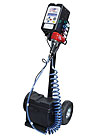
Assemblers don’t necessarily need a torque transducer to error-proof pulse tool operation. Other technologies can do a similar job. For example, the QC Air Tool Qualifier from Ingersoll-Rand Industrial Technologies (Annandale, NJ) tracks pulse tool performance by monitoring airflow.
The device learns the airflow “signature” of a good run-down. It then compares subsequent run-downs to that profile, alerting the operator to any outliers, says Scott White, Ingersoll-Rand’s global category manager for fastening. The device works with pulse tools with or without an automatic shut-off. It detects cross-threaded fasteners, rehit fasteners and premature trigger release. It also monitors fastener count and cycle time.

This pulse tool uses a cam-and-roller slip clutch to transfer energy from the casing to the anvil. Because it does not pressurize the hydraulic fluid, the tool rarely needs an oil change. Photo courtesy SigmaSix LLC
Not for Every Application
With recent improvements, pulse tools are typically accurate to ±15 percent of the specified torque. That’s good enough for most high-volume applications, but it’s not as good as a computer-controlled DC electric nutrunner, which is accurate to ±2 percent of the specified torque.“On the other hand, a pulse tool can apply 950 newton-meters of torque without a reaction arm,” says Moore. “You couldn’t do that with an electric nutrunner.”
As much as pulse tools have advanced, the tools still have some drawbacks. Soft joints remain an issue with pulse tools. Because the anvil slows as resistance to rotation increases, a soft joint will slow the speed of the anvil dramatically and extend run-down time. This can be countered to some degree by using a larger pulse tool.
Joints with significant prevailing torque can also be an issue with pulse tools. If the prevailing torque is close to the final torque, the tool may shut off or stall prematurely. This can be countered by using a larger pulse tool without an automatic shut-off.
Finally, although the interval between scheduled maintenance sessions has grown longer, most pulse tools still require regular upkeep. The hydraulic fluid needs to be changed periodically, as do the springs, O-rings and gaskets. For some assemblers, these maintenance costs may outweigh the ergonomic and productivity benefits of the tool.
The bright side, notes Michigan Pneumatic’s Arthur, is that maintenance intervals are predictable. “With an impact tool, you don’t know how long the tool is going to run,” he says. “The operator could let the tool run too long [after the fastener is fully tightened], and the parts will wear against each other needlessly.” As a result, an impact tool could need maintenance sooner than expected.

Gloves do more than just protect the hands. They also help assemblers grip parts and tools. Photo courtesy Gloves OnLine Inc.
Gloves Improve Grip, Performance and Safety
Gloves are the easiest and cheapest method of hand protection for any assembly process. Gloves do more than just protect the hands, however. Gloves also improve performance by giving assemblers a better grip on parts and tools.When choosing gloves for a particular assembly process, engineers should consider the three F’s-function, fiber and fit.
There are hundreds of options for industrial gloves. Which to choose depends on the task to be performed. Leather gloves are good for general assembly applications, when hand protection is more important than grip performance. Coated gloves help operators grip parts and keep hands dry in wet conditions. Coated gloves are good for working with power tools, because they increase the operator’s grip and provide abrasion protection. Look for gloves with a foam coating, since that enhances grip better than solid coatings.
The three most common coatings are nitrile rubber, polyurethane and latex. Nitrile rubber is best for resisting grease, oil and other petroleum-based products, and, of course, it’s waterproof. Polyurethane provides extra abrasion resistance and extended wear. Latex is waterproof, but it will blister and delaminate when in contact with petroleum-based products.
The shell or body of a glove provides its feel, strength and durability, but it’s the fibers inside that make it breathable and comfortable. Some fibers also enable gloves to resist cuts. Fiber choices include cotton-polyester blends; textured nylons; aramid, such as Kevlar; and polyethylene, such as Dynemma.
Gloves are not one-size-fits-all. It is imperative that the glove fits, well, like a glove. Lack of a sure and comfortable fit is the reason most workers do not use gloves.
For more information on work gloves, call 877-456-8313 or clickhere.
