Flexible Fixtures for Automated Assembly
Researchers have developed a hexapod-based reconfigurable fixture that can be used to assemble a family of automotive headlights.
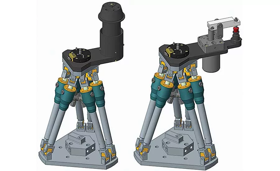
These flexible fixtures consist of a hexapod, a tool changer, and two examples of modular workpiece-locating assemblies. Illustrations courtesy Jožef Stefan Institute
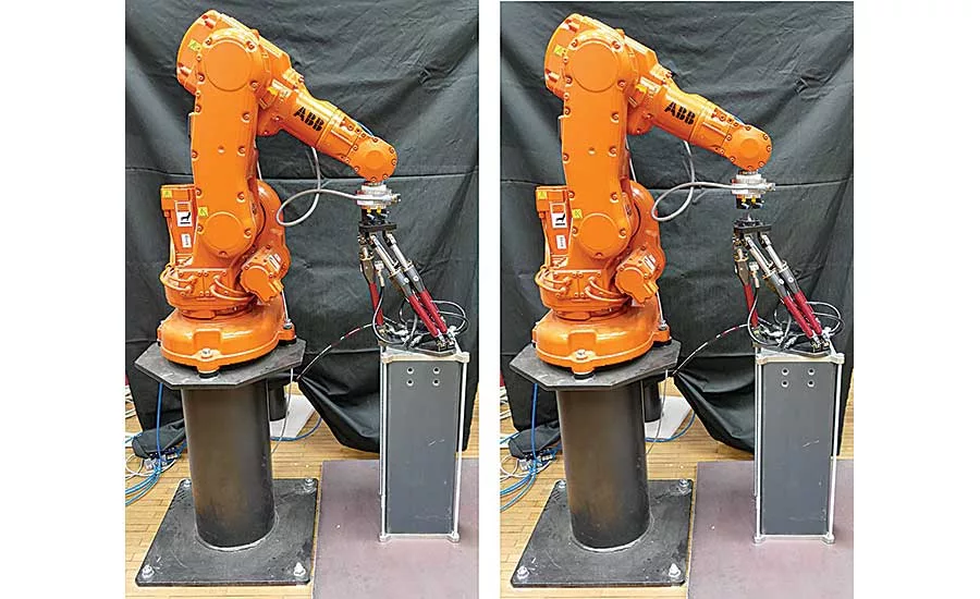
To reposition the flexible fixture, a six-axis robot connects with a tool changer on the top plate (left). When the fixture is in position, the hexapod’s brakes are activated and the robot releases the tool changer (right). Photos courtesy Jožef Stefan Institute
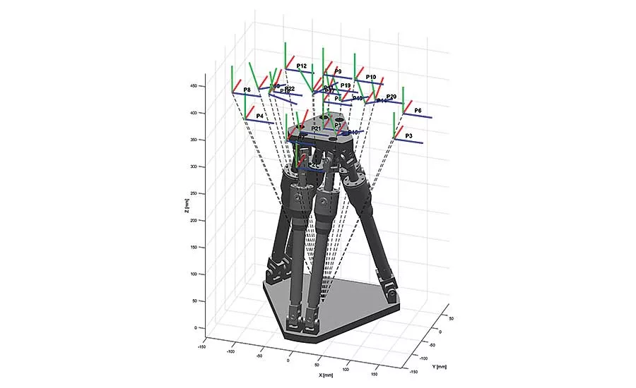
To measure the position of specific points on the hexapod, the researchers used a 3D optical measuring system. Illustration courtesy Jožef Stefan Institute
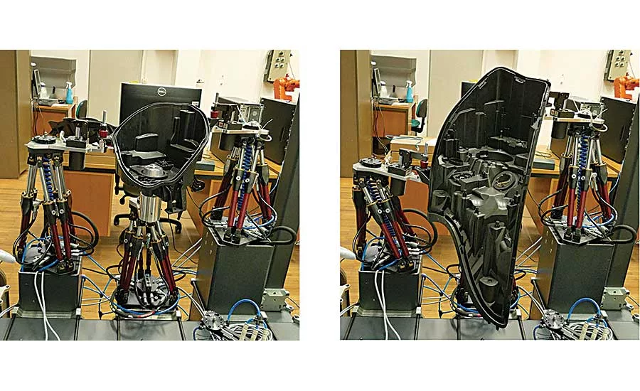
To test their flexible fixtures, the researchers used them to assemble two automotive lights with very different geometry but similar assembly operations. Photos courtesy Jožef Stefan Institute
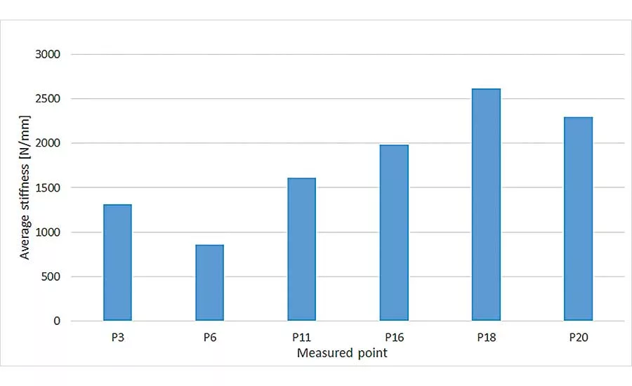
The stiffness of the hexapod was measured at six points. The hexapod was locked, and the robot applied forces in six directions. Average stiffness in the X and Y directions were measured at 1,328.8 newtons per millimeter and 1,333.4 newtons per millimeter, respectively. In the Z direction, the stiffness was considerably higher. Source: Jožef Stefan Institute
Fixtures are essential to most assembly and machining processes. Their design is vital, as they have a direct effect on productivity, cost and quality. It is estimated that 40 percent of rejected parts stem from inappropriate fixturing.
Most fixtures are designed for a specific part or operation. However, making, storing, retrieving and setting up dedicated fixtures can be costly. Indeed, such fixtures can represent 10 to 20 percent of the total cost of an assembly system. Moreover, dedicated fixtures typically require long lead times to produce. As a result, dedicated fixtures are only feasible for high-volume, low-mix production.
On the other hand, flexible fixtures are designed to be reusable. Of course, a true one-size-fits-all fixture is not feasible, since there are an infinite variety of workpiece geometries and operations requirements. But, flexible fixtures can be designed to fit a family of similar products that require similar operations. Compared with dedicated fixtures, the initial costs of flexible fixtures are higher, but their total cost of ownership is lower because they can accommodate multiple products.
Flexible fixtures are not incompatible with automation. In fact, they can be part of reconfigurable automated assembly systems. Changeover can be achieved with or without worker assistance. Such an approach will allow automation to be adopted by small and medium enterprises (SMEs), where product variety is high and batches are small.
To meet the demands of flexible assembly, we have developed a reconfigurable fixture based on an unpowered Gough-Stewart parallel mechanism, also known as a hexapod. The positioning of the fixture is done by a robot.
Related Research
A variety of reconfigurable and flexible fixtures have been developed over the years. For example, Harry Asada, Ph.D., and researchers at the Massachusetts Institute of Technology developed a reconfigurable modular fixture system. The system relies on vertical and horizontal clamps attached to a table with magnetic chucks. Depending on the workpiece geometry, a robot can reposition the modules and then lock them in place. The system was developed for production operations in which batch sizes range from 20 to 100 units. However, the use of magnetic chucks makes the system useful only for nonmagnetic workpieces.
A modular, programmable, conformable clamping system for fixturing turbine blades during machining was developed by researchers at Carnegie-Mellon University. It uses a hinged octagonal frame positioned around an arbitrary section of the blade. The lower half of the frame employs pneumatic plungers that, in their released state, are free to conform to the blade profile. A high-strength belt is used to press the convex part of the blade against the locked plungers.
Looking for quick answers on assembly and manufacturing topics? Try Ask ASM, our new smart AI search tool. Ask ASM
The most flexible approach is to use special robots as fixtures. General Motors and NASA developed special servo actuators for work-holding. These robotic actuators enabled production down to the lot size of one. However, due to their high cost, such actuators are not feasible for SMEs.
Flexible Fixture
Our fixture is based on hexapods. A hexapod can move in all six degrees of freedom. Our hexapod is unpowered. It must be moved into position manually or by robot and then held in place with a locking sleeve or hydraulic system.
The hexapod has two plates connected by six links. The base plate is rigidly connected to the robotic cell. The top plate is equipped with a modular workpiece-locating assembly and the tool side of a robotic tool changer. The tool changer is what enables the robot to reposition the hexapod.
Each of the six links of the parallel mechanism is composed of two preloaded Cardan joints and a prismatic joint with an integrated hydromechanical brake. The Cardan joints connect the link to the top and base plate and are designed to minimize backlash. The prismatic joint is used to lock the mechanism in place once a suitable configuration has been achieved.
The workpiece-locating assembly is the part of the fixture that contacts the workpiece. Its design depends on the workpiece geometry and manufacturing operations. As a result, we could not design a truly universal locating system. Instead, we came up with a reconfigurable approach offering limited flexibility to accommodate a family of workpieces.
To assess the capability of our flexible fixture, we used it to assemble a family of automotive lights. The design of the workpiece-locating assembly was based on an analysis of the common geometric features of the whole product family. We determined that mounting holes were a suitable feature for locating and clamping the workpiece. However, different models have different hole diameters. To make the locating assembly compliant with the whole family of parts, the centering pins are interchangeable. To minimize human interaction and speed up the reconfiguration process, the pins are exchangeable by a robot. A pneumatic lever clamp holds the workpiece in place.
Preliminary testing revealed that additional support was needed during assembly. So, we designed a new locating assembly that used a centering element to supplement the clamping system. The centering element locates and supports the hole for the main bulb of the light. Different models have different diameter holes so the seating elements are exchangeable by robot as well.
Evaluating the Fixture
Our first task was to evaluate the hexapod itself. For automated assembly, a reconfigurable fixture must be able to position the workpiece precisely and repeatably. So, we needed to assess the stiffness of the locked mechanism and the positional accuracy of the hexapod after repositioning.
The hexapod’s locking mechanism would be critical for accuracy and repeatability. When the brakes are released and the hexapod is free to move, it is positioned by the robot. When the brakes activate, a holding force acts upon the rods in the hexapod’s links. If locking the brakes disrupts the final position of the fixture, the hexapod cannot be properly positioned regardless of the positioning accuracy of the robot.
Another important characteristic is the stiffness of the locked mechanism. During robotic assembly, forces are exerted on the workpiece that are consequently transmitted to the fixtures. If the fixture is not stiff enough, those forces will displace both the fixture and the workpiece.
Our test setup was composed of a fixture with the baseplate attached to a stiff metal pillar secured to the floor. Our robot was an ABB IRB 140 equipped with a Delta force and torque sensor from ATI Industrial Automation and a QC-30 tool changer from DESTACO.
To facilitate positional measurements, no locating assembly was used. To measure the position of specific points on the hexapod, we used an Athos 3D optical measuring system from GOM. Accurate to ±0.04 millimeter, the system uses stereo triangulation
to obtain surface data in the form of a point cloud. For each measurement, three to five scans were made to get enough geometric data of the points on the top and bottom hexapod plate. From these measurements, three points on the hexapod’s top plate were extracted and their positions relative to the bottom plate were calculated. By measuring three different points on the hexapod’s platform, we were able to determine the positional and rotational displacements relative to the hexapod base.
Positional repeatability was measured in 20 configurations. The selected points were distributed equally inside the workspace envelope so we could measure the effect of the brake’s actuation on the final position of the hexapod. The robot was used to reposition the hexapod.
The reference position and orientation was measured twice. The first measurement was made while the hexapod was connected to the robot and still compliant. Afterwards, the mechanism was locked, the tool changer uncoupled, and the end-effector of the robot retracted. Then, the second position measurement was made to determine the position and orientation of the top plate. In this way, we were able to determine if the hexapod locking had any influence on positional accuracy.
Analysis of the data revealed that the mean positional displacement due to the position locking was 0.08 millimeter with standard deviation of 0.08 millimeter. The mean value of the rotational displacement was 0.9 milliradian and with standard deviation of 0.0005 milliradian.
Our tests showed that using the tool changer to connect the robot to the hexapod produced some negative effects. During uncoupling, the plates are pushed apart by approximately 1 millimeter. The force is considerable and caused visible movement of the robot. Fortunately, this problem could be solved by using an electromagnetic gripper.
The biggest displacements were observed in the X-direction and the smallest in the Z-direction. This is a consequence of the nonlinearity of the mechanism stiffness in different directions and configurations. Because the force resulting from uncoupling the tool changer acts perpendicularly to the top plate, forces in different directions are exerted on the hexapod mechanism links. When a load is applied in the Z-direction, the angles between the mechanism links and the forces acting on them are generally smaller than in the X and Y directions, resulting in better stiffness and locking repeatability.
The accuracy of the 3D scanning system was too low to reliably measure the repeatability of the fixture, but the fixture’s performance exceeded our expectations. More precise measurements will be needed to determine the actual repeatability of the locking mechanism, but we determined that the fixture could reliably be used to assemble car lights.
The stiffness of the hexapod was measured at six of the 20 points used for the repeatability measurements. The hexapod was locked, and the robot applied forces in six directions (positive and negative translation along all axes of the hexapod’s base coordinate system and positive and negative rotation along the Z axis). Forces were generated by pushing the fixture 0.3 millimeter in each direction while the mechanism was locked. The force magnitudes varied depending on the combined stiffness of the robot and the hexapod in a given configuration and direction. Forces and torques were measured using a sensor mounted to the robot’s wrist. A set of 3D measurements were made before and after the application of force in each direction to determine the magnitude and direction of displacements. The position and orientation of the top plate was measured relative to the hexapod bottom plate to avoid measuring deformation of other components, such as the pillars.
These measurements gave us an overview of the stiffness characteristics of the hexapod throughout its workspace. Stiffness was calculated taking into account only the components of forces and deformations collinear to the direction of the external load. The average stiffness across all the points in all directions was approximately 1,780 newtons per millimeter.
Different stiffness values were observed in different directions. Average stiffness in the X and Z directions was measured at 1,328.8 newtons per millimeter and 1,333.4 newtons per millimeter, respectively. The values are similar because of the symmetry of the mechanism. In the Z direction, the stiffness was considerably higher—2,323.4 newtons per millimeter. This is to be expected, as the angle between the hexapod legs and load in this direction is the smallest. More stiffness in Z direction is beneficial, since most assembly operations exert forces along this axis.
Case Study Evaluation
To test our fixture, we used it to assemble a variety of automotive lights.
Assembling a light is a multistep process. First, the plastic housing is manually inserted into a fixture in a semiautomatic machine. Next, an assembler installs various subcomponents, such as a light-height adjustment motor, a bulb holder, and a metal heat shield. Then, the components are secured with self-tapping screws driven by a servo screwdriver.
Typically, each light model requires two fixtures: one for the left light and one for the right. When a new light model is introduced, a new fixture must be designed and manufactured. This increases lead times and raises costs. Moreover, the fixture for the old part must be stored for 10 to 15 years so spare parts can be produced in small batches a few times a year. And, since automotive suppliers typically produce multiple models of lights at the same time, storing different fixtures becomes expensive.
Our goal was to develop a robotic assembly cell, equipped with flexible passive fixtures, that could assemble a family of lights with minimal changeover time and cost. Two different automotive lights were chosen for the first experiments. We chose these models because they have very different geometry but require similar assembly operations.
Three reconfigurable fixtures were used for work-holding. Two of them were equipped with pneumatic clamps, and one was equipped with a centering element.
Changeover between models is a three-step process. First, the three hexapods are repositioned to a predetermined model-specific configuration. Then, the centering pins of the clamps and the centering elements are removed and stored in special pallets using a dedicated robotic end-effector. Finally, new centering elements are installed.
The robotic reconfiguration was successfully tested multiple times. A UR10 robot from Universal Robots was used to move the hexapods. The exchange of modular elements was performed manually.
We also evaluated how the fixture would perform during assembly. The entire assembly sequence—inserting a part, installing subcomponents, and driving screws—was accomplished with the workpiece held in place by the reconfigurable fixtures. Several assembly cycles were successfully performed. The insertion of the light housing was reliable even when gripping was suboptimal. No accuracy issues were observed while installing the subcomponents. The forces exerted on the workpiece did not result in any observable fixture displacement.
Although testing is in a preliminary stage and further experiments are required, the reconfigurable fixtures show great potential to reduce the fixture costs and to shorten the changeover times.
Editor’s note: Martin Bem, Miha Deniˆsa, Timotej Gaˆspar, Jaka Jereb, Robert Bevec and Igor Kovac are co-authors of this article.
Looking for a reprint of this article?
From high-res PDFs to custom plaques, order your copy today!


