Wire Processing
Robot-Assisted Assembly of Wiring Harnesses for Airplanes
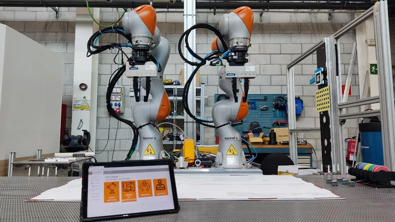
The researchers’ system consists of two cobots from Kuka Robotics.
Wire harness assembly in the aerospace industry is highly manual, with production defined by multiple references and small batches. Although complete automation of the production process is not feasible, a robot-assisted approach could increase the efficiency of existing production methods.
To that end, we have developed a dual-arm robotic system for workbench configuration and cable routing for harness assembly. Using the CAD file for the wire harness, our system generates trajectories in real-time to complete the initial assembly tasks, automatically dividing the whole job between each robot. Our system has been validated in a production environment using different wire harness designs, obtaining promising results and metrics.
CAD-based robot programming has been around for some time now, applied in many industrial sectors. From welding to spraying, numerous manufacturing applications take advantage of CAD data to generate robot trajectories. Even so, the approach is usually found in scenarios without uncertainty, where the placement of all the elements of the application is perfectly known beforehand. Wire harness assembly is a trickier prospect, since individual wires are flexible and therefore unpredictable.
The application of robotics to wire harness assembly has been studied since the early days of technology. For example, in 2014, researchers at Tohoku University in Sendai, Japan, developed a robotic system to assemble a wire harness for an automotive instrument panel. The system consists of three vision-guided, six-axis robots positioned in front of an instrument panel frame. The third robot helps with positioning and grasping the harness, while the other two run the wires.
Following a different direction, researchers at the University of Padua in Italy detailed a system in 2021 that uses a collaborative robot for harness taping operations, while people perform the work of routing and connecting wires.
In the aerospace sector, researchers at Raytheon and the University of Connecticut unveiled a system in 2020 in which a vision-guided cobot works with a human technician to pin wires in connectors.
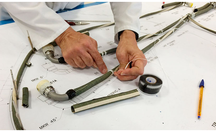
An assembler puts together a wire harness using a 2D drawing as a template. Photo courtesy Basque Research and Technology Alliance
Assembling Harnesses for Airplanes
Wire harness assembly in the aerospace sector is characterized by a large number of references and small batch sizes. Indeed, in many cases, the wire harness is unique. Assembly is entirely manual, and the process can take up to a month for large harnesses.
Looking for quick answers on assembly and manufacturing topics? Try Ask ASM, our new smart AI search tool. Ask ASM
The process starts in the design office, where engineers receive the CAD files for the harness from the OEM. These references are transformed into a 2D drawing. Additionally, all the information about each wire is listed in a document, defining its path and its connectors.
Next, all the wires and connectors are sent to the production area along with the drawing, printed at a 1-to-1 scale, and the document with the wire information. The drawing is affixed to a “nail board” to use as a template. Operators configure the board by placing pins at specific points of the drawing, such as endpoints and bifurcations, to guide the wires. These pins are crucial to maintaining the shape of the wire harness.
When the board is prepared, assemblers begin picking up wires and guiding them along the drawing. This step can take a long time, since operators must constantly study the documentation to verify the initial and final points of each wire and its route, especially if they are not familiar with the harness.
Once all the wires are routed, operators perform various tasks, such as taping or connector welding.
This workflow highlights the impact of information loss from CAD design to production. All the information generated by the CAD designers, which could be used to automate some steps of manufacturing, is diluted in the process, forcing assemblers to review the documents over and over during production. Therefore, a CAD-based robot programming system could significantly enhance the harness assembly process.
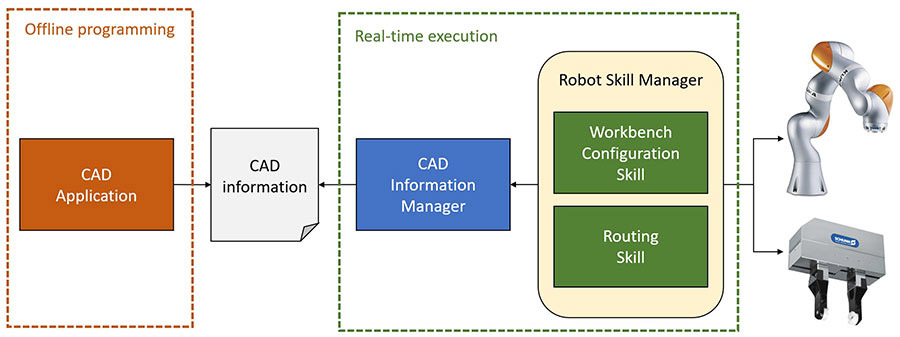
The authors propose a two-step workflow: offline programming for data extraction from CAD models, and real-time execution of robot tasks based on CAD data. Photo courtesy Basque Research and Technology Alliance
Proposed Approach
We propose a system to carry out the initial steps of the assembly process, specifically the nail board configuration and cable routing. Our goal is to offer a complete system linking CAD-based robot programming with real-time task execution. Thus, we propose a two-step workflow: offline programming for data extraction from CAD models, and real-time execution of robot tasks based on CAD data.
In the initial phase, an Offline Programming Framework assists engineers in defining the main elements of the wire harness, such as wire paths, endpoints and pin placement points. The module allows engineers to interact with the CAD models, extracting information by clicking on the 2D drawing of each reference. As a result, several XML files are generated for the Real-Time Execution Framework of the robotic system.
In the second phase, the Real-Time Execution Framework acquires the information generated in the offline programming phase and uses it to configure the board and route the cables. Specifically, the framework includes two modules, one to load the CAD information and transform it into the robotic coordinate system, and a second offering workbench configuration and routing skills. These modules interpret the CAD information and reconfigure robot trajectories in real time based on the received data.
Offline Programming Framework
The starting point of manual wire harness assembly is a 2D CAD drawing of the harness. Our goal is to use this same drawing to program the robot, using the offline programming paradigm. Specifically, we created software to interact with the CAD software and extract information about the positions of the harness to be sent to the robotic system.
During manual assembly, workers pay particular attention to the endpoints, as well as to the intersections. Therefore, the application allows defining these points intuitively in the drawing just by clicking on the desired position. It will generate a set of points in the CAD coordinate system, where each of the points is defined by a translation vector. As the application uses a 2D drawing, all the Z values of the vectors are set to 0. Even so, any desired value could be assigned to the vectors’ Z element, creating different layers. These points will be used both for cable routing as well as for CAD calibration in further steps.
Once all the relevant points are specified, the user will be able to define different paths along the points, describing the possible routes for the cables in the wire harness. Thus, a set of paths will be generated where each path is a subset of the point set and defines the complete cable route from start to end.
Finally, each of the cables of the wire harness is assigned to a specific path. As each cable has a unique identifier, a list of pairs will define the assignation of each wire to a unique path. The sets of points, paths and pairs will be exported in XML format to be exploited by the Real-Time Execution Framework.
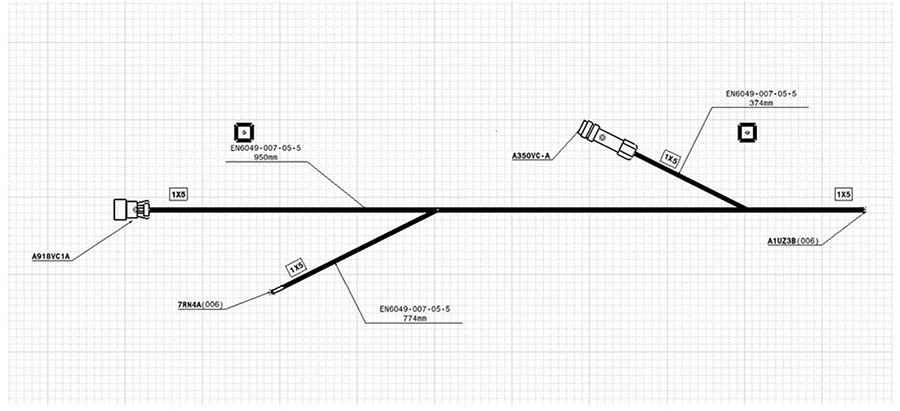
This image shows a typical 2D drawing of a wire harness. Photo courtesy Basque Research and Technology Alliance
Real-Time Execution Framework
Once the Offline Programming Framework generates the harness information, the Real-Time Execution Framework uses the data to generate robot trajectories to configure the board and route the cables. The idea is to use the same setup in these two initial steps, even for different harness types, and without any additional modification from assemblers.
Nevertheless, it is necessary to calibrate the robot setup to have knowledge of the geometric information of the different elements of the dual-arm robotic layout. Specifically, the following transformations and coordinate systems are defined in the robot cell.
First, there is a nominal CAD origin in the workbench, which is calibrated for each robot of the dual-arm system. Therefore, homogeneous transformation matrices define both the position and orientation of the nominal CAD origin in each robot’s base frame.
As it is complex to manually place a 2D drawing precisely in the robot cell’s CAD origin, the Real-Time Execution Framework includes a CAD calibration step. This CAD calibration will calculate the offset between the nominal CAD coordinate system and the real CAD origin, an offset generated due to small errors in the placement of the drawing on the board. A transformation matrix represents this offset both in translation and orientation.
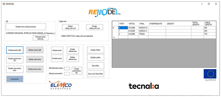
The authors developed software to interact with the CAD system and extract information about the positions of the wire harness to be sent to the robotic system. Photo courtesy Basque Research and Technology Alliance
To ensure the capability to modify the robot tools and adapt the robot movements accordingly, another matrix defines the transformation between the flange of the robots and each of their tools’ tool center point.
Finally, each robot has a pin feeder near its base to provide the pins that will be placed in the CAD drawing, as well as a cable dispenser near robot 1 with a calibrated pose to grasp each wire.
The availability of this information allows a fast and reliable adaptation to modifications in the layout, requiring only updating the coordinate system information to rearrange the application.
Finally, the Real-Time Execution Framework relies on two modules to perform the different tasks to configure the workbench and route the cables.
The CAD Information Manager manages all the CAD data received from the Offline Programming Framework in XML file format. Specifically, the module loads the XML files and offers different queries to get information about pin positions and routing paths. Additionally, due to errors in the positioning of 2D drawings on the workbench, this module provides a function for calculating the offset matrix based on the position of calibration points in the drawing and the position of the robots.
The Robot Skill Manager manages the robots and grippers, offering different skills to perform each step of the assembly process. Specifically, there are two skills available: configuration of the workbench by placing the routing pins in the selected points of the CAD drawing, and routing the cables based on the defined paths.
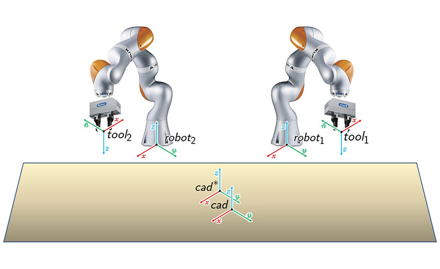
Before the robots can install pins and route wires, the system must be calibrated. Photo courtesy Basque Research and Technology Alliance
Implementation
Our system was implemented on a real setup to validate our approach. Our setup consists of two articulated robots equipped with parallel grippers to manipulate both pins and wires. An important aspect of the setup is the capability to sense and control the applied forces and execute compliant movements to ensure the quality of the tasks.
Two LBR iiwa 7 robots from Kuka Robotics are the workhorses of the system. These lightweight, seven-axis cobots are equipped with torque sensors in each joint. Both arms are placed side by side in front of a workbench for wire harness assembly. The compliant capabilities of the robots allow them to execute force-controlled movements; this ensures safe execution of movements for pin placement and cable routing, avoiding damage to the parts due to excessive force.
Each robot is equipped with a WSG 050-110 gripper from Schunk. These servo-electric grippers have a maximum stroke of 110 millimeters and a maximum gripping force of 80 newtons. The gripper fingers are custom-made with a planar shape. Both sides are covered by a thin foam to protect the cables, and both sides have a vertical groove to grip the pins.
Additionally, the setup includes several components related to harness assembly:
- Workbench where all the elements of the wire harness are placed and managed.
- A metal sheet where operators place the CAD drawings.
- Pins, 60 millimeters long, equipped with a magnetic base that can be attached to the metal sheet.
- Two pin trays placed near each robot.
- A cable feeder consisting of five cable rolls, placed on a side of the workbench. The tip of each cable includes a small clip with magnets to facilitate gripping by the robot.
Additionally, the system includes several features that take advantage of the robot hardware and improve the process:
- Compliant motion for both pin placing and cable routing. Each pin and cable grasp and release movement includes compliance in the Z axis to avoid excessive forces that could damage the part. The routing paths also include compliance in the X and Y axes to facilitate routing and alleviate the effects of entanglements.
- Variable gripping force ensures a suitable grasp for both pins and cables without any damage to the parts.
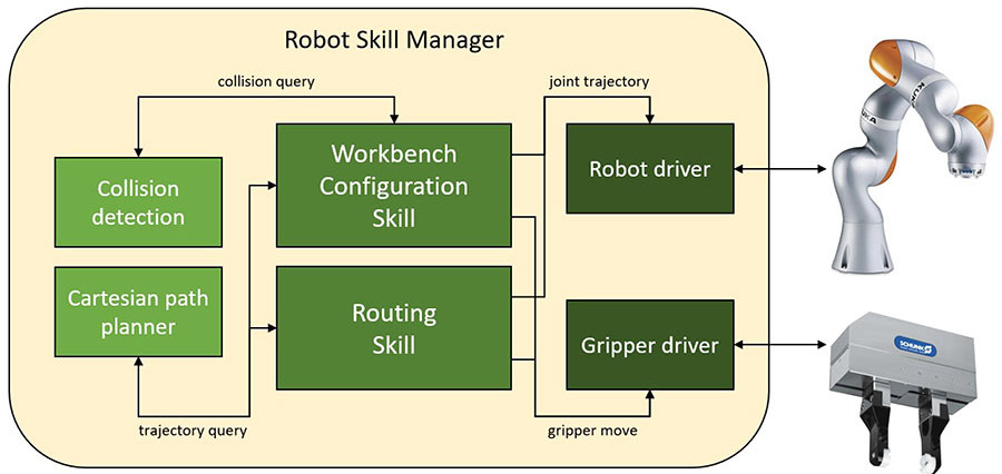
The Robot Skill Manager includes internal modules to assist the robots in configuring the nail board and routing the wires. Photo courtesy Basque Research and Technology Alliance
Validation
We tested our setup with wires between 0.5 and 3.5 millimeters in diameter and lengths between 1 and 2 meters.
To cover the complete scope of the system, our test included both offline programming and real-time execution steps.
The Offline Programming Framework aims to facilitate the generation of robot programs by nonexpert users, so our tests focused on usability. We measured how fast engineers can define the wire and pin information on CAD drawings of new wire harnesses. The test involved five subjects. Each subject was asked to define the pin positions and cable routes for five wire harnesses.
To add variability to the process, three of the CAD files were 2D drawings and two were 3D drawings. Although the most common scenario is to use 2D CAD files, in some cases OEMs may only provide 3D drawings of the wire harness.
The results show that subjects completed the task in a mean time of around 5 minutes, 40 seconds. It is worth mentioning that subjects improved their processing time in each iteration with each CAD file type (2D and 3D), pointing out that they quickly got used to the application and were able to carry out the task in less time. In fact, subjects improved their times by an average of 23 percent from the first time using the software to the last.
Another interesting point is that processing time for all subjects increased significantly when they shifted from 2D to 3D CAD models. As expected, moving around the drawing in 3D required more time than the equivalent task in a simpler 2D plane.
The second phase of our validation testing aimed to assess the performance of the Real-Time Execution Framework, comparing it with the manual work carried out by assemblers.
In our system, an assembler guides the robots to the calibration points of the drawing using a 6D joystick and launches the robot program. Afterwards, the robots configure the workbench and route all the cables. Assemblers only intervene in the calibration step, leaving the execution of configuration and routing to the robots.
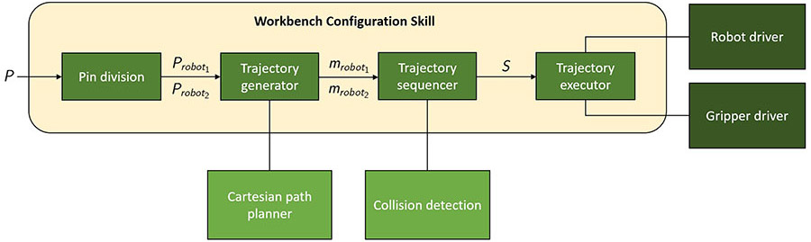
This diagram shows the programming for configuring a nail board. Photo courtesy Basque Research and Technology Alliance
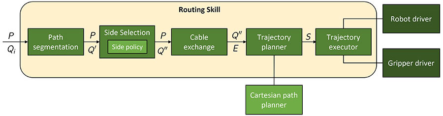
This diagram shows the programming for routing wires. Photo courtesy Basque Research and Technology Alliance
To compare manual and robotic approaches fairly, a baseline was calculated with the time spent by assemblers on the tasks. The baseline calculation procedure involved five subjects. Each subject was asked to configure the workbench and route all the cables for two wire harnesses. For each harness, subjects were provided with some documentation with pin positioning guidelines and a table with the route for each wire. Each subject decided on his own how to manage the documentation, checking the data at any moment of the task without any restriction.
Our results show that subjects spent a mean time of 57 and 51 minutes configuring the workbench for each wire harness, while the routing took 2 hours, 31 minutes, and 1 hour, 53 minutes. Additionally, the efficiency of the tasks was between 40 and 43 percent, which points out that subjects spend more than half of their time consulting the documentation.
In our system, assemblers only need to guide both arms to the calibration points, leaving the workbench configuration and routing task to the robots.
Our results show that subjects spent a mean time of 57 and 48 minutes in the calibration step, improving the results in the second harness design due to the familiarization with the calibration procedure.
For the workbench configuration, the robots required 1hour, 4 minutes, and 1 hour, 40 minutes. For the routing process, the robots needed 3 hours, 26 minutes, and 3 hours, 46 minutes. In both cases, the time required by the robots for each task in both wire harness references was similar. Additionally, the robotic system obtained a success rate of 100 percent for both pin placement and cable routing operations.
Comparing the manual and robotic approaches, our results show that for both tasks—workbench configuration and routing—the manual system is faster than the robotic system, specifically around 50 percent faster in the second reference. Operators can carry out the pin pick-and-place operations and the routing of cables faster than the robotic system, especially the routing. (In takes approximately 20 seconds for one robot to pass a wire to the other.)
On the one hand, the total time for the manual operation is 36.4 and 56.1 percent faster for each wire harness design. On the other hand, our comparison points out that even if the total task time is greater in the robotized approach, the operator time is significantly reduced at 72.6 and 70.7 percent, and obviously, the idle times in which assemblers review the documentation are reduced to zero.
Our results show the feasibility of the approach, even if the complete task time is greater with the robotic system.

These images show the robots installing pins (left) and routing wires. Photo courtesy Basque Research and Technology Alliance
An important aspect of the robotic approach is scalability. In the robotic system, the assembler only takes part in the calibration process, which lasts around 1 minute. If we consider the baseline timing information, routing a single wire takes around 25 minutes, including the documentation check and the task itself. Therefore, a five-wire harness would involve around 2 minutes of routing, while a 25-wire harness would increase the time to 10 minutes.
Additionally, we would expect that assemblers would spend more time checking documentation, increasing the idle times, the routing time per cable, and the possibility of assembly errors. This would make automation more justifiable.
For future research, the first issue would be to parallelize the robots’ movements as much as possible to speed up the task. Another important issue is to evolve the current hardware and physical elements of the cell to simplify some tasks for the robots, since our initial setup imitates how manual operations are performed by people. An evolution of the setup would also speed up and stabilize the robotic process, making it more efficient and profitable.
This could be achieved, for instance, by designing more complex grippers or integrating vision-based calibrations of the harness drawing. Such integration would reduce the need for manual intervention, consequently reducing calibration time.
In addition, the use of active cable dispensers would allow the assembly of larger and thicker wires, reducing the friction between the wire and the elements of the workbench and assisting the routing. Finally, the current routing execution relies on compliant movements to ensure its success. This could be improved by adding a more complex force-based controller that reacts to excessive forces caused by entanglements.
Editor’s note: This article is a summary of a research paper co-authored by Maite Ortiz de Zarate, senior researcher, and Aitor Ibarguren, Ph.D., senior researcher, at the Basque Research and Technology Alliance. To read the entire paper, click here.
For more information on wire harnesses, aerospace applications and robotics, read these articles:
Assembling a Wire Harness for Deep Space
Software Aids Design of Wire Harness for NASA’s New Rocket
Conquering Complexity in the Design and Assembly of Wire Harnesses for Aerospace Applications
Looking for a reprint of this article?
From high-res PDFs to custom plaques, order your copy today!


