Manufacturing Software
Cyber-Physical Systems in Automotive Assembly
Magna International has automated the process of routing and positioning vehicle bodies on a high-mix, high-volume assembly line.
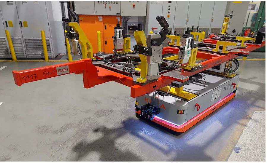
This image shows a prototype FTPD mounted on an automated guided vehicle.
Contract manufacturers such as Magna International enable established automotive OEMs to outsource serial production, manage ramp-downs, and test new vehicle concepts without placing additional loads on their own production networks. For automotive startups, Magna can help mitigate risk by providing access to established operations, skilled personnel, and robust supply chains.
Our plant in Graz features a body-in-white (BIW) assembly line, a paint shop, and general assembly operations. The plant specializes in low-volume vehicle programs. It can integrate all powertrain technologies on a single assembly line while balancing production loads across different products.
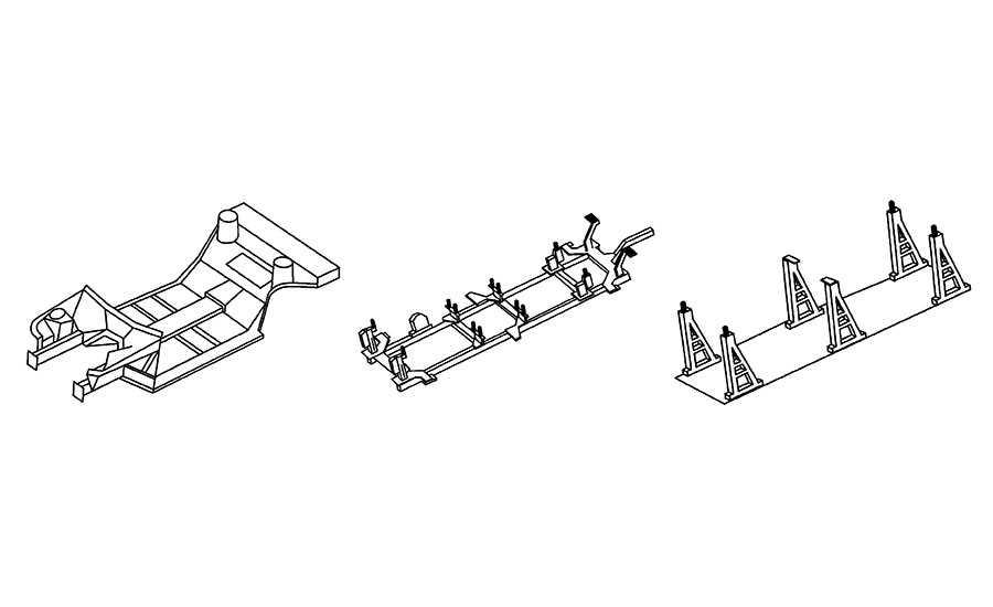
The elements of a multi-product BIW assembly line include the vehicle underbody, a TPD, and stationary jigs. Illustration courtesy Magna International
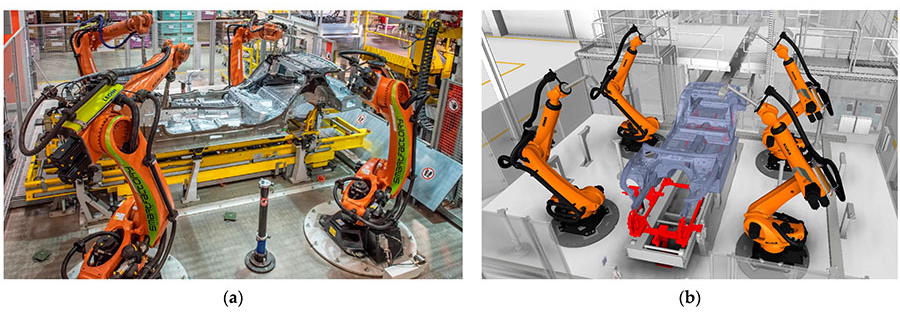
These images show our inline measurement station for inspecting BIW assemblies. The four six-axis robots are equipped with optical metrology sensors. The 3D model (right) shows the underbody highlighted in blue and the TPD highlighted in red. Photo courtesy Magna International
Contract manufacturing presents unique technological challenges, particularly when multiple vehicle variants are produced on a shared assembly line.
To ensure dimensional accuracy and structural stability of a BIW, the position of the underbody on the line must be maintained precisely and consistently at every stage. This is crucial for welding, fastening and inspection applications. Typically, this is achieved by geometrically aligning and clamping the underbody to stationary jigs via central mounting points.
However, when model variants are assembled on the same line, an additional construction element becomes necessary: transportable positioning devices (TPDs). These devices act as carriers that adapt the varying underbodies to a uniform mounting and clamping concept and maintain geometric alignment at each assembly station. Upon entering the body shop, each underbody is assigned to a dedicated TPD, which accompanies it through the entire BIW process until it is handed over to the paint shop.
The positioning devices are systematically rotated. Surplus units are stored and reintroduced into production as required. Our factory in Graz can operate 50 TPDs simultaneously per product, depending on the model mix and volume.
Geometric deviations in the TPDs, which result from wear, translate directly into deviations in the vehicle structure. Such deviations can incur quality-related costs, including scrap and rework. This problem is compounded by the fact that the locators used to geometrically align the underbody on the TPD cannot be accessed for measurement during production. Instead, the TPDs must be taken off-line periodically for inspection and maintenance, which is costly and time-consuming.
Looking for quick answers on assembly and manufacturing topics? Try Ask ASM, our new smart AI search tool. Ask ASM
To solve the problem, we developed a cyber-physical inspection system to identify and reject TPDs that are out of spec. We created a system to map the causal geometric relationships between TPDs and vehicle bodies, enabling us to extrapolate deviations from measurement data using “big data” analytics.
Not content to rest on our laurels, we then used that experience to develop a cyber-physical assembly system that enables us to configure advanced, flexible TPDs on demand.
The BIW Manufacturing Process
BIW manufacturing follows a sequential process. Sheet metal parts and pre-assemblies are joined to form subgroups, which are then assembled onto the underbody. Allocated to a TPD, the underbody passes through fully automated framing and welding stations. Side panels are attached using mechanical joining methods. Doors and flaps are mounted. And, surface finishing is completed before handover to the paint shop.
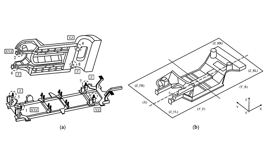
A set of four holes in an underbody correspond with four locating pins on a TPD. Illustration courtesy Magna International
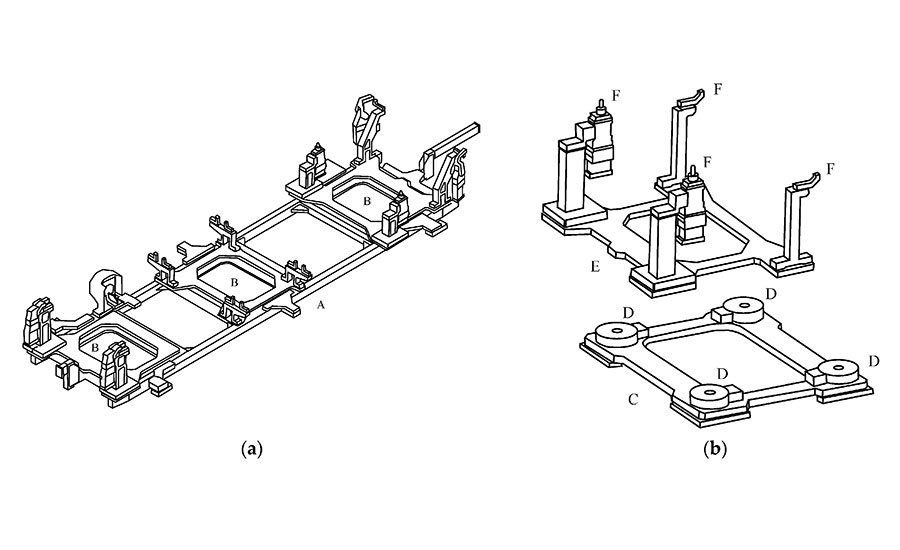
Magna’s FTPD consists of several elements. The left drawing shows the main frame (A) with three docking modules (B). The right drawings show a docking module, which consists of a main module (C) with four locking mechanisms (D); and an interchangeable docking plate (E) with four receptacles (F). Illustration courtesy Magna International
Assembly sequencing and identification are managed via a manufacturing execution system (MES). Tracking is accomplished directly by the PLC, as well as bar codes or RFID tags.
Traditionally, geometric quality control is done by pulling small samples of subassemblies and finished bodies off the line for inspection by coordinate measurement machines (CMMs). Based on these measurements, process adjustments are defined, executed, verified and documented.
However, assembly deviations caused by individual TPDs cannot be reliably detected through sampling because their occurrence probability is too low relative to the sample size. As a result, TPD inspection and maintenance must be done at regular intervals.
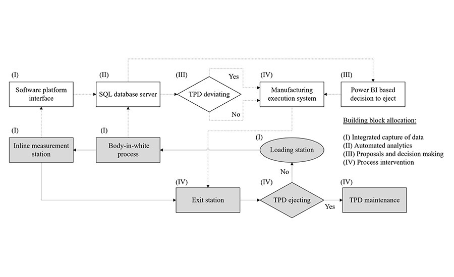
This is the flowchart for our cyber-physical inspection system. Physical elements are shown in gray. Computational elements are shown in white. The process to differentiate between deviating and non-deviating TPDs is illustrated with decision points. Illustration courtesy Magna International
The Flexible Positioning Concept
To solve the problem, we implemented three robot-based optical inline measurement stations on the BIW line. Our goal was to accelerate process stabilization; improve process control; ensure documentation of quality; and minimize scrap, rework and downtime.
Located at critical points in the process flow, each station uses four robots equipped with high-accuracy optical sensors for image processing, line triangulation, and shadow analysis to monitor approximately 100 key features. Each feature is measured in 3 to 4 seconds. Measurement accuracy is ±0.25 millimeter for correlation with coordinate systems, ±0.2 millimeter for static tests, and ±0.3 millimeter for dynamic process tests.
The stations incorporate state-of-the-art compensation mechanisms to maintain metrological reliability. Each station employs calibration artifacts that enable the compensation of robot-induced thermal drift and support automated recalibration routines. These internal compensation cycles are complemented by regular external verification procedures, including correlation checks with CMMs.
A set of four holes in an underbody correspond with four locating pins on a TPD. Any positional deviation in a TPD can therefore affect the position of the underbody in the X, Y or Z axes.
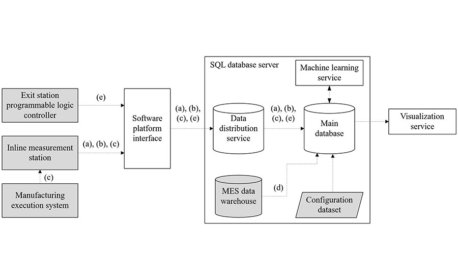
This flowchart shows the data that our system collects, where it goes, and how it’s processed. Illustration courtesy Magna International
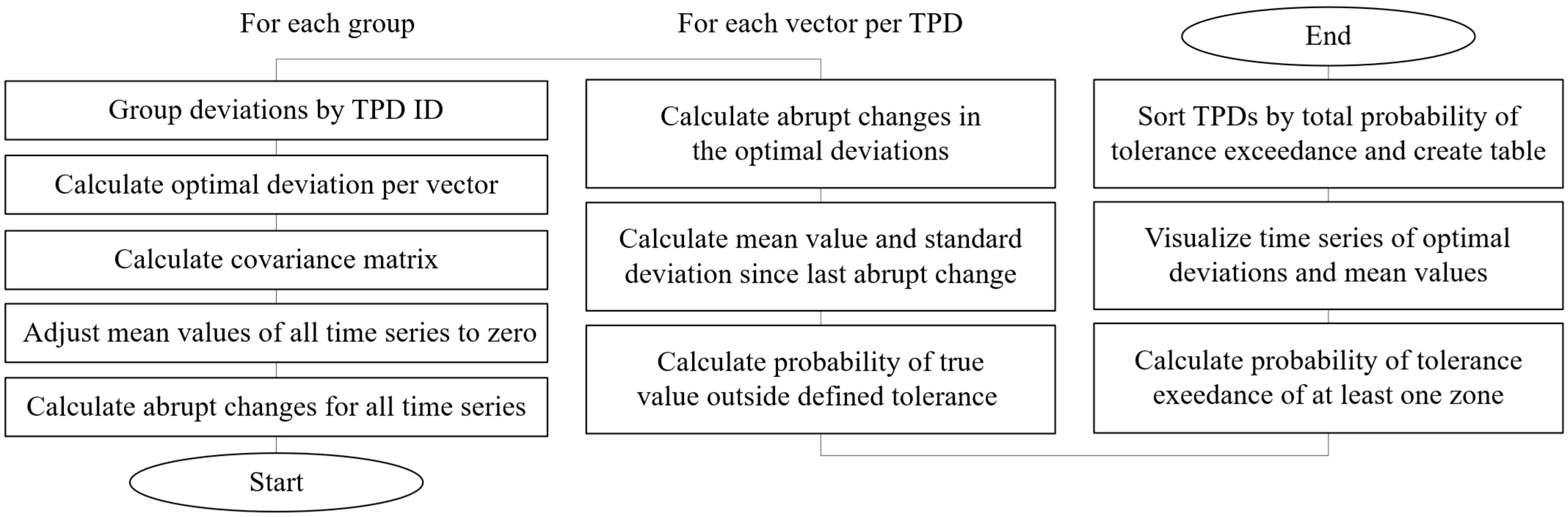
This flowchart shows the programming sequence for analyzing TPD data. Each block represents an algorithmic operation. Illustration courtesy Magna International
Our original TPD concept requires substantial adaptation for each new product variant. And, because the TPDs are made by an external supplier, a set number of them must be ordered based on planned production volumes. As a result, little flexibility exists to accommodate fluctuations in unit quantities or changes in the production program over the course of a multiyear project.
To enhance efficiency and increase flexibility, we developed an advanced TPD. Our new flexible transportation positioning device (FTPD) enables rapid, model-specific reconfiguration within the BIW manufacturing process. It efficiently adapts to different vehicle types using interchangeable docking plates equipped with variant-specific receptacles.
The core of the system is a rigid frame that can accommodate multiple modules. Each module provides a precise mechanical interface for attaching interchangeable docking plates. The docking plates carry bearing faces, consoles and tensioning elements that accurately align, mount and clamp different underbody models relative to the vehicle coordinate system.
The docking plates are plate-shaped elements that can be mounted onto a main module manually or with automated handling systems. For precise positioning, each docking plate incorporates retractable clamping bolts on its underside, projecting vertically downward. These bolts engage with corresponding zero-point clamping and locking mechanisms, also known as quick-change pallet systems. These mechanisms are integrated into the main module, ensuring repeatable positioning within defined tolerance limits.
The main modules are equipped with integrated media interfaces that supply compressed air, electrical power and signal transmission. Once the bolts are pneumatically engaged, the docking plate forms a mechanically rigid and precision-aligned docking module together with the main module fixed to the main frame.
The design allows different docking plates to be used with a single main module. Different docking plates equipped with variant-specific receptacles can be exchanged accurately without modifying the main frame or main modules. This enables the production of different vehicles using the same structural equipment.
The device consists of at least three main modules and three interchangeable docking plates with one plate per module. To reconfigure the FTPD for a new model variant, only the clamped docking plates need to be exchanged. The main frame and main modules remain unchanged, which significantly reduces changeover time and initial investment. The design also reduces quality issues caused by geometric deviations of the TPD over time.
Our FTPDs adhere to ISO 14638, ISO 5459 and ISO 1101 standards, and they maintain a tolerance for geometrical fixture deviations at ±0.2 millimeter, which is consistent with our original TPD design.
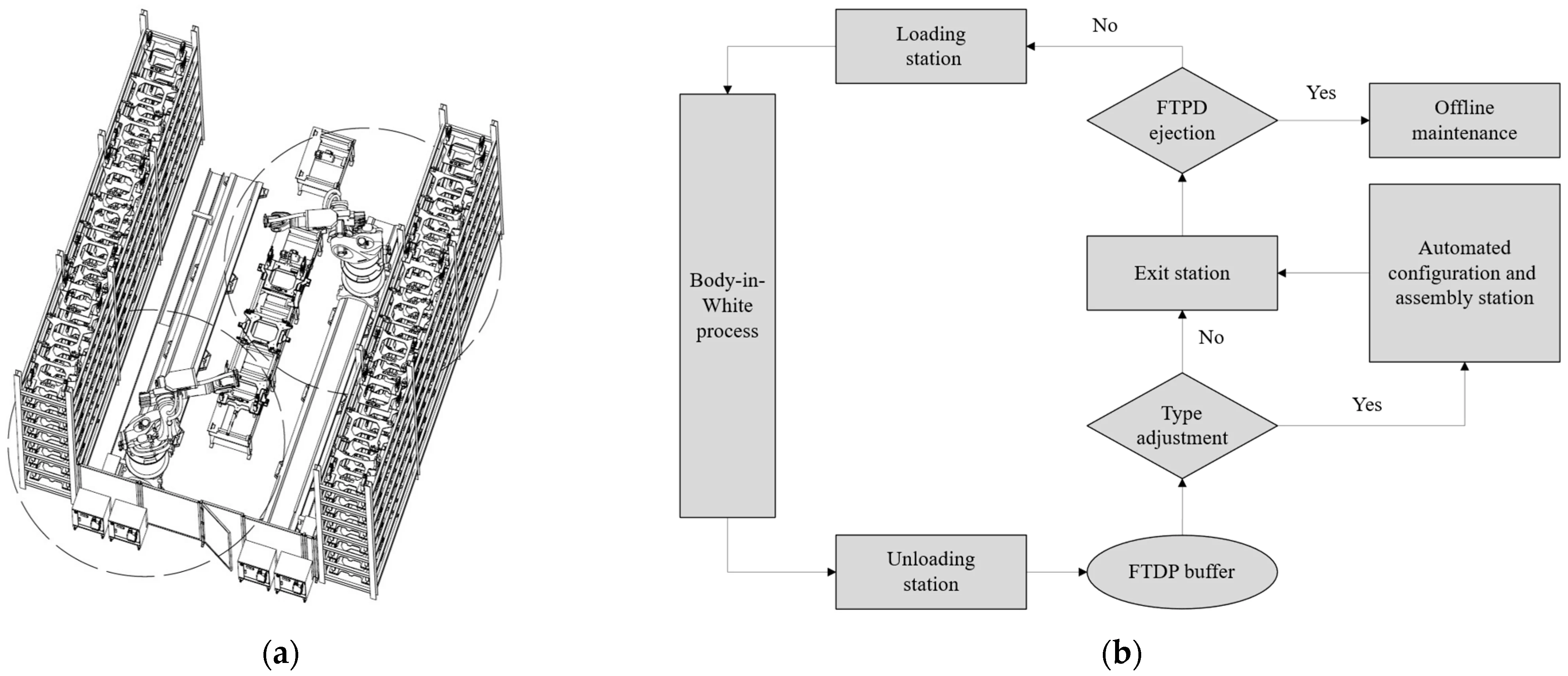
This drawing on the left shows the layout of our automated configuration and assembly station for FTPDs. The circles indicate the reach of the robots. The flowchart on the right shows the decision tree for a generic BIW assembly process. Illustration courtesy Magna International
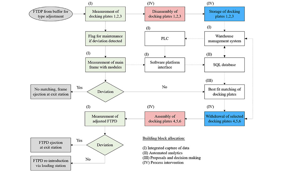
This is the station flowchart for replacing a complete set of docking plates, transitioning from plates 1 to 3 to plates 4 to 6. Shown are the external elements (gray), measurement elements (green), handling elements (red), warehouse elements (blue), and simplified computational elements (white). Illustration courtesy Magna International
Cyber-Physical Inspection System
We developed a cyber-physical inspection system to identify TPDs that are out of spec. Data are captured by sensors, processed and fed back to actuators and digital interfaces. Specifically, the system collects five types of data: assembly measurements, production time stamps, the unique identifier of each assembly, the unique identifier of each TPD, and maintenance time stamps.
Product configuration data are also integrated and accessed by a machine learning service, which runs a Python 3.10 script executed daily before the first shift. Visualization is conducted using Microsoft Power BI. Daily updates are provided by an on-premises report server. Data older than 36 months are archived monthly.
A Python script within the machine learning service detects deviating TPDs based on data input and configuration datasets.
Long-term observations confirm that external factors, such as material batches or environmental conditions, did not affect the results. The algorithm was validated by ejecting out-of-spec TPDs and verifying the corresponding deviations through CMM measurement.
Out-of-spec TPDs are selected by the MES, identified by the RFID reader, and ejected by the exit station’s PLC for offline maintenance.
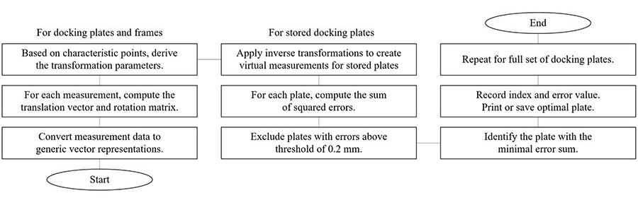
This flowchart shows the programming sequence for reconfiguring FTPDs. Photo courtesy Magna International
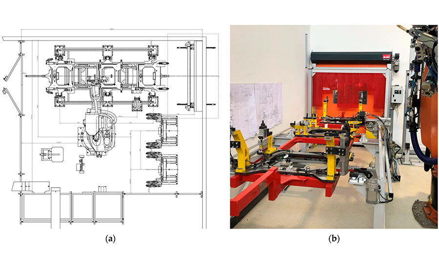
This drawing and photo show our setup for reconfiguring FTPDs. Photo courtesy Magna International
Cyber-Physical Assembly System
The on-demand configuration and assembly of FTPDs is centered around a parts storage magazine consisting of interchangeable docking plates tailored to specific products. The core process involves selecting appropriate docking plates and matching them precisely to generic main frames, with the target of minimizing tolerance stack-ups between components.
The warehouse management system selects the plates, using measurement data from an automated optical measurement system. The docking plates on incoming FTPDs are measured. After disassembly of the docking plates, the main modules attached to the main frames are measured. The docking plate set with the best fit for the current main frame is then identified via a matching algorithm. Disassembly and assembly of the FTPDs are then performed automatically by robots.
After configuration and assembly, the FTPD is measured to verify conformance with specifications.
Seven categories of data are needed to configure the FTPDs: docking plate measurements, main module measurements, FTPD measurements after configuration, warehouse location, FTPD unique identifier, time stamp and cycle counter.
The objective of the best-fit matching algorithm is to compensate for deviations in single components by selecting the most appropriate combination of modules and docking plates in terms of tolerance. The tolerance for geometrical deviations of individual parts is set at ±0.1 millimeter, while the tolerance for the assembled combination is set at ±0.2 millimeter.
FTPDs are fed into the configuration and assembly station based on information provided by the MES.
Results
Our cyber-physical inspection system resulted in substantial reductions in time, effort and cost, although these metrics are not quantified in this paper due to confidentiality constraints.
Our cyber-physical assembly system has completed prototype testing and is ready for procurement, with full system setup and pilot deployment planned for the next customer project. The design of the FTPD, along with the patented configuration and best-fit matching method, demonstrated stability and suitability for high-volume deployment.
Editor’s note: This article is a summary of a research paper co-authored by Christoph Kribernegg, project leader for body-in-white, Magna International; Stefan Koerner, research associate, Know Center Research GmbH, Graz; and Martin Schellander and Franz Haas, research associates, Graz University of Technology. To read the entire paper, click here.
Looking for a reprint of this article?
From high-res PDFs to custom plaques, order your copy today!


